Filter, high-frequency module, communication device and filtering method
a filter and high-frequency module technology, applied in the input field, can solve the problems of limited miniaturization of the device, large device size, and limit to the miniaturization
- Summary
- Abstract
- Description
- Claims
- Application Information
AI Technical Summary
Benefits of technology
Problems solved by technology
Method used
Image
Examples
first embodiment
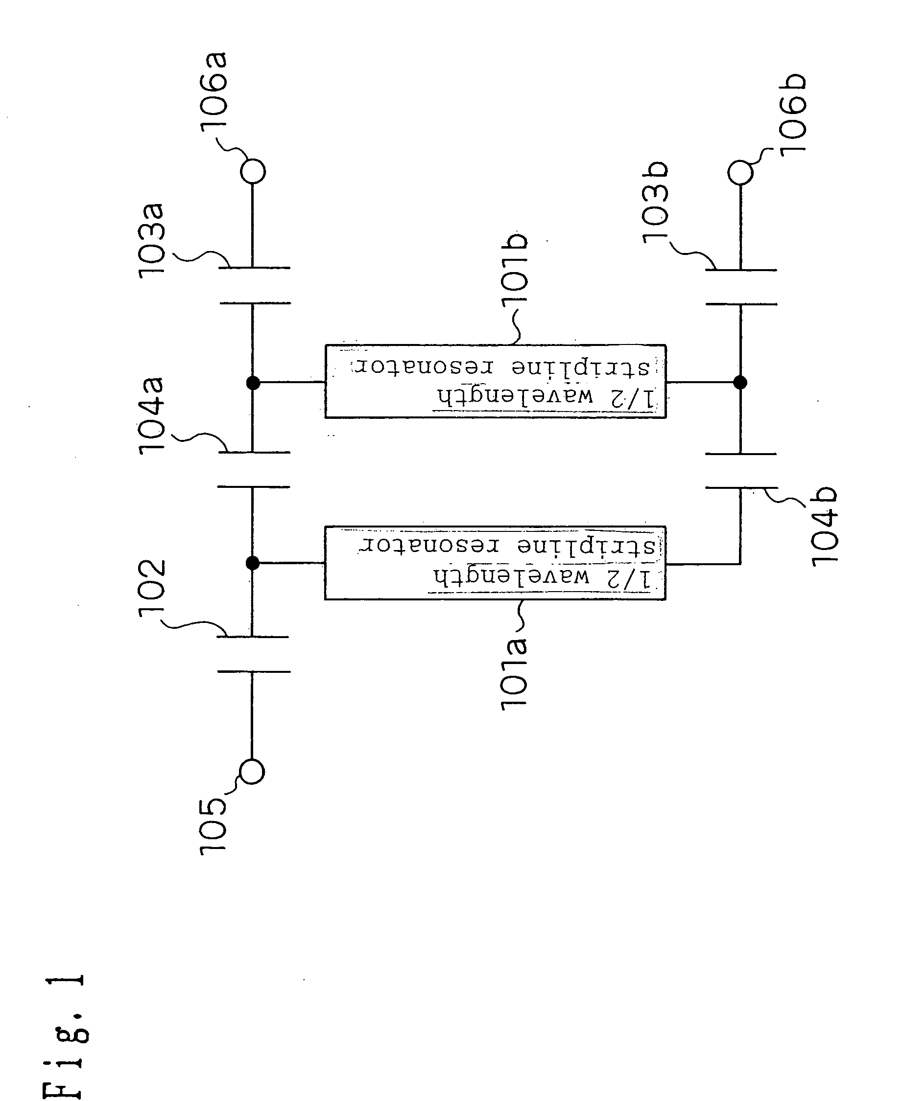
[0224]FIG. 1 is one of equivalent circuit diagrams of a band-pass filter of an unbalanced input (output)-balanced output (input) type according to a first embodiment of the present invention.
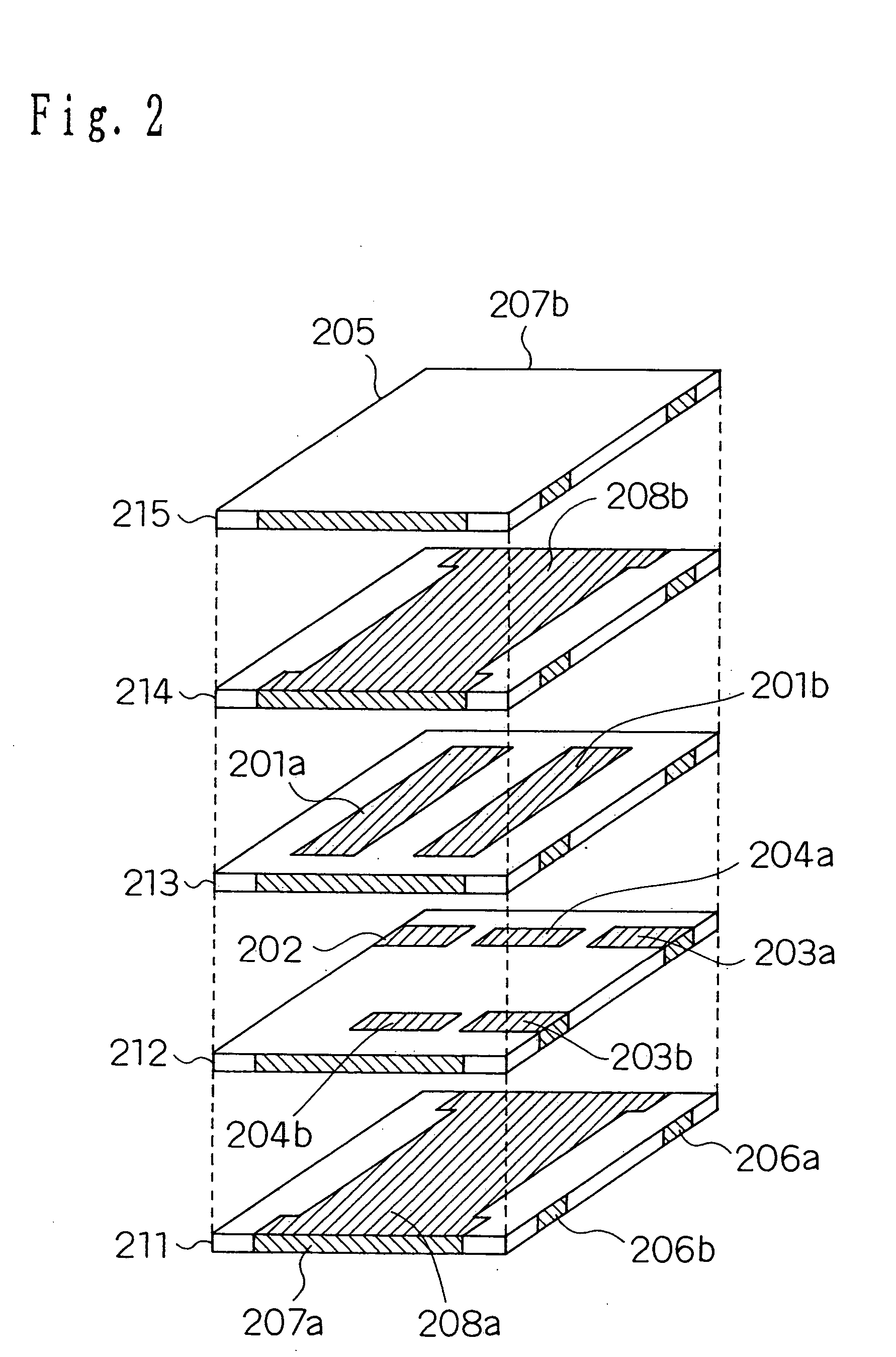
[0225] According to this configuration, stripline resonators 101a and 101b are electromagnetically coupled. The stripline resonators 101a and 101b substantially have the length of ½ wavelength (electrical length, same hereafter) of desired resonant frequencies. One end of the stripline resonator 101a is connected to an unbalanced input (output) terminal 105 via a coupling capacitance 102, and both ends of the stripline resonator 101b are connected to balanced output (input) terminals 106a and 106b via coupling capacitances 103a and 103b. Furthermore, two inter-section coupling capacitances 104a and 104b are connected between both ends of the stripline resonators 101a and 101b.
[0226] Next, operation of the band-pass filter shown in FIG. 1 will be described. The signal inputted from the unbalanc...
second embodiment
[0237] Next, FIG. 5(a) shows an equivalent circuit configuration of the band-pass filter of the unbalanced input (output)-balanced output (input) type for controlling the frequency of the attenuation pole according to the second embodiment of the present invention.
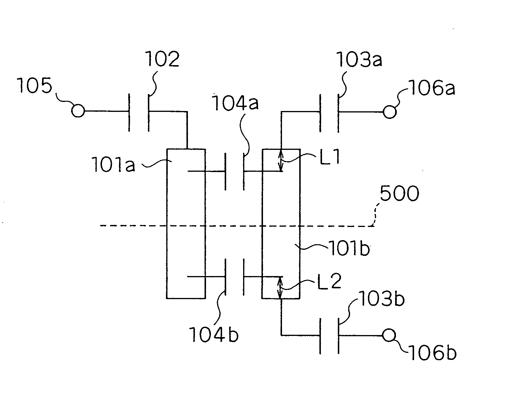
[0238] As shown in FIG. 5(a), this is the configuration wherein, as to the equivalent circuit configuration of the unbalanced-balanced laminated filter in FIG. 1, the inter-section coupling capacitance 104a as an example of a first capacity element of the present invention and the inter-section coupling capacitance 104b as an example of a second capacity element are placed at distances L1 and L2 in a central direction from both ends of the pair of stripline resonators 101a and 101b of substantial ½ wavelength of the resonant frequencies respectively. It is possible to realize the laminated structure for implementing this equivalent circuit by changing coupling positions of the inter-section coupling capacitances in FIG. 2...
third embodiment
[0249]FIG. 8 is an equivalent circuit diagram of the unbalanced-balanced band-pass filter according to a third embodiment of the present invention.
[0250] According to this configuration, there are one stripline resonator 801a of substantial ½ wavelength of the desired resonant frequencies and a pair of stripline resonators 821a and 821b of substantial ¼ wavelength of the desired resonant frequencies. The stripline resonators 821a and 821b are placed in parallel with the stripline resonator 801a and mutually in series in order to be electromagnetically coupled respectively. One end of the stripline resonator 801a is connected to an unbalanced input (output) terminal 805 via a coupling capacitance 802. Ends of the respective stripline resonators 821a and 821b are connected to balanced output (input) terminals 806a and 806b via coupling capacitances 803a and 803b, and the other ends of the respective stripline resonators 821a and 821b form the short circuit ends. Furthermore, an inter...
PUM
 Abstract
Description
Claims
Application Information
 - R&D
- Intellectual Property
- Life Sciences
- Materials
- Tech Scout
- Unparalleled Data Quality
- Higher Quality Content
- 60% Fewer Hallucinations
Browse by: Latest US Patents, China's latest patents, Technical Efficacy Thesaurus, Application Domain, Technology Topic, Popular Technical Reports.
© 2025 PatSnap. All rights reserved.Legal|Privacy policy|Modern Slavery Act Transparency Statement|Sitemap|About US| Contact US: help@patsnap.com


