
Quadrifilar helical antenna

a helical antenna and quadrifilar technology, applied in the field of quadrifilar helical antennas, can solve the problems of increasing the size of the printed circuit board on which the antenna is mounted, increasing the antenna cost, and imposing losses and bandwidth limitations

Inactive Publication Date: 2006-02-02
SKYCROSS INC
View PDF29 Cites 66 Cited by
  • Summary
  • Abstract
  • Description
  • Claims
  • Application Information

AI Technical Summary

Problems solved by technology

It is known that such quadrature matching techniques, such as hybrid couplers and baluns, disadvantageously increase the size of the printed circuit board on which the antenna is mounted.
The couplers and baluns also increase the antenna cost, and each additional component operative with the antenna imposes losses and bandwidth limitations.
However, when the QHA is installed in close proximity to a radio transceiver handset, the handset structure can induce electromagnetic wave reflections that influence the QHA's radiation pattern and impedance, much like a ground plane.
Obviously, such effects negatively influence the antenna's performance, and can be particularly troublesome if the communications system employs dual signal polarizations.

Method used


Image

  • Quadrifilar helical antenna
  • Quadrifilar helical antenna
  • Quadrifilar helical antenna

Examples


Embodiment Construction

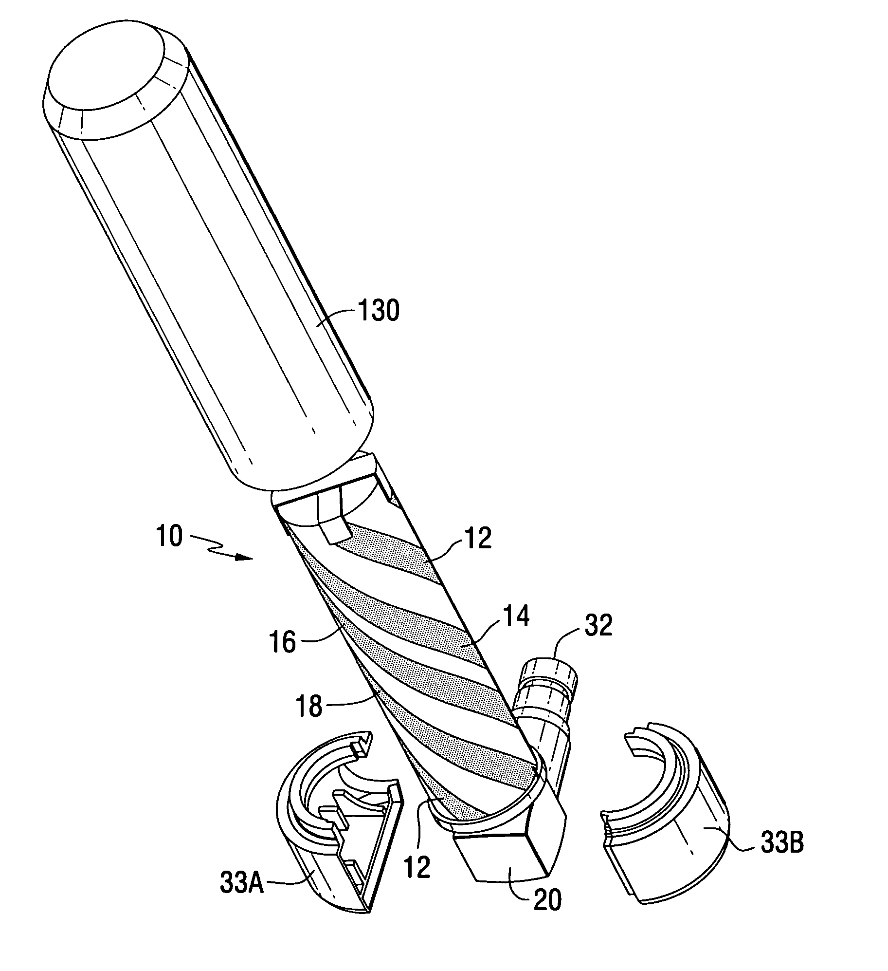
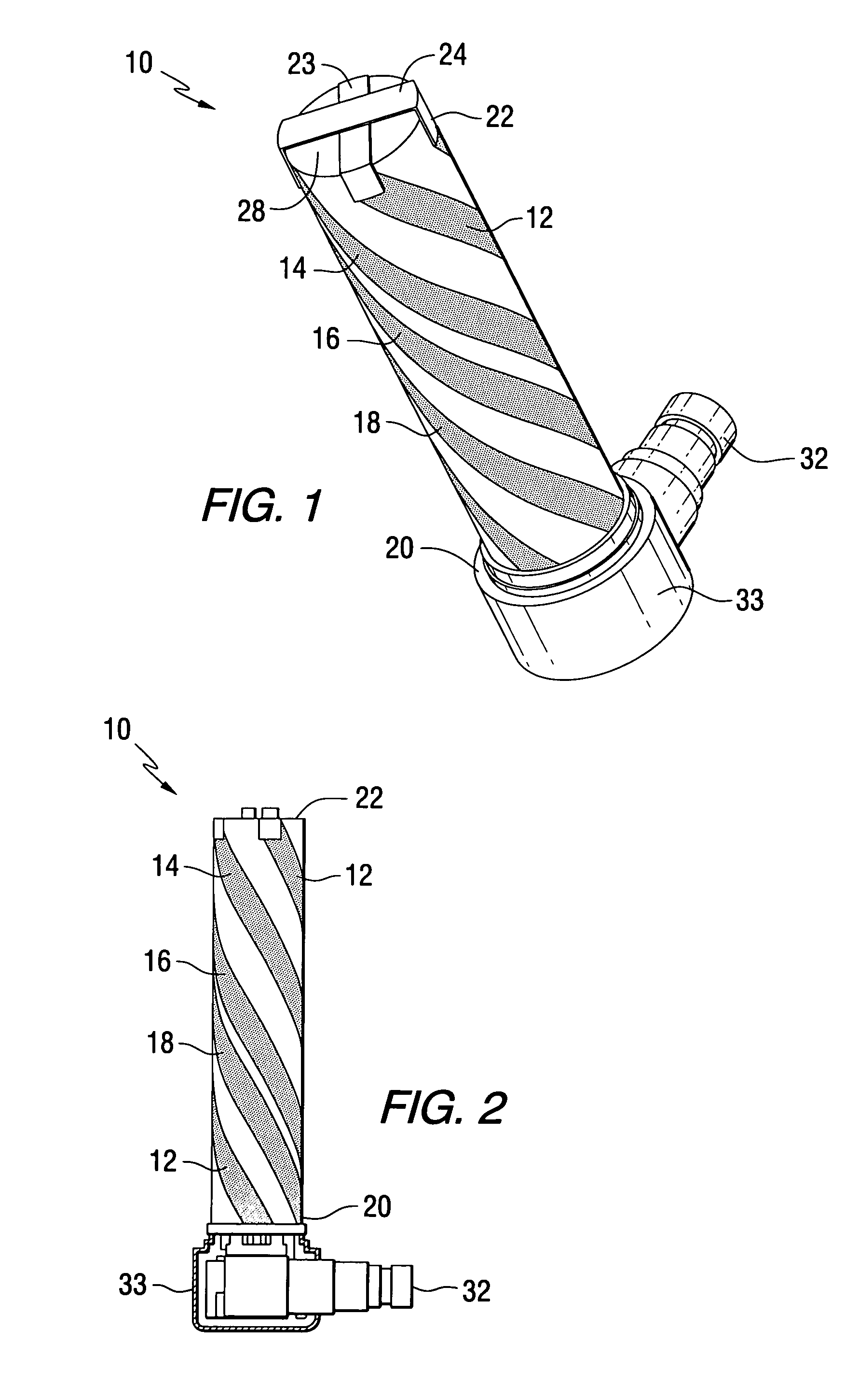
[0025] Before describing in detail the particular antenna apparatus and a method for making the antenna according to the present invention, it should be observed that the present invention resides in a novel and non-obvious combination of hardware elements and process steps. Accordingly, these elements have been represented by conventional elements in the drawings and specification, wherein elements and method steps conventionally known in the art are described in lesser detail, and elements and steps pertinent to understanding the invention are described in greater detail.

[0026] This invention relates to an antenna responsive to a signal source supplying quadrature related currents to each of four filars, comprising s short pair of filars and a long pair of filars. The antenna further employs a simple, low cost, low loss matching element that takes advantage of the circularly polarized gain provided by the antenna filars. In one embodiment the antenna provides advantageous gain in...


PUM


Abstract

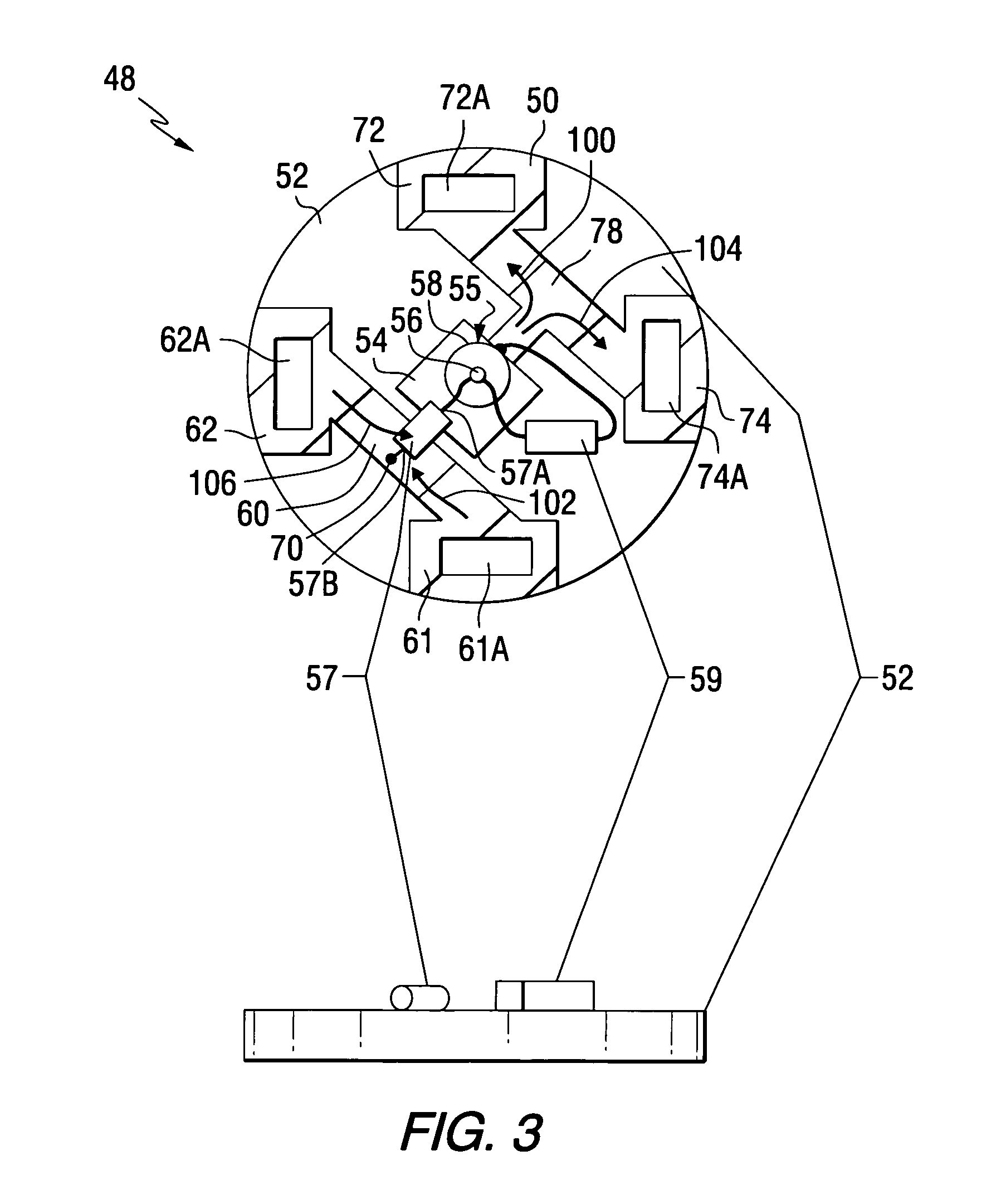
A quadrifilar helical antenna comprising two pairs of filars having unequal lengths and phase quadrature signals propagating thereon. A conductive H-shaped impedance matching element matches a source impedance to an antenna impedance. The impedance matching element having a feed terminal at the center thereof from which current is supplied to the two filars of each filar pair disposed about an edge of the impedance matching element and symmetric with respect to a center of the impedance matching element. The impedance matching element further comprises a reactive element for matching the antenna and source impedances.

Description

[0001] The present application claims the benefit under Section 119(e) of the provisional application filed on Jul. 28, 2004 and assigned application No. 60 / 592,011.FIELD OF THE INVENTION [0002] The present invention relates to an antenna for use in a satellite communications link, and in particular to a quadrifilar helical antenna (QHA) for use in a satellite communications link. BACKGROUND OF THE INVENTION [0003] A helical antenna comprises one or more elongated conductive elements wound in the form of a screw thread to form a helix. The geometrical helical configuration includes electrically conducting elements of length L arranged at a pitch angle P about a cylinder of diameter D. The pitch angle is defined as an angle formed by a line tangent to the helical conductor and a plane perpendicular to a helical axis. Antenna operating characteristics are determined by the helix geometrical attributes, the number and interconnections between the conductive elements and the feed arrang...

Claims


Application Information

Patent Timeline
Patent Type & Authority Applications(United States)
IPC IPC(8): H01Q1/36
CPCH01Q11/08H01Q1/38
Inventor O'NEILL, GREGORY A. JR.FUGATE, MURRAYJO, YOUNG-MINFARRAR, JOHN C.LEE, MYUNG SUNGOH, SE-HYUNLEE, JOO MUNYOON, JIN HEECHOI, SANG OKHAN, EUN SEOK
Owner SKYCROSS INC
Learn More