Image reading apparatus

Inactive Publication Date: 2006-02-02
SEIKO EPSON CORP
View PDF8 Cites 19 Cited by
  • Summary
  • Abstract
  • Description
  • Claims
  • Application Information

AI Technical Summary

Benefits of technology

[0040] According to this configuration, when the sensor module is transported to the sub scanning-direction end, the support member is housed into the space that is present on the side of the second protruding portion in the main scanning direction, without abutting the second protruding portion. Accordingly, the support membe

Problems solved by technology

However, since the contact image sensor module has a shallow depth field, the image reading apparatus cannot clearly read a document placed at a position away from a platen surface of a document platen.
Image reading apparatuses described in JP-A-2003-37712 and JP-A-2003-37713, each including a plurality of optical systems, can clearly read a reflective document and a transmissive document by changing an optical path in response to the document However, the image reading apparatuses described in JP-A-2003-37712 and JP-A-2003-37713, the optical systems of which have a complex configuration and a long optical path, have the problem in which they are high in manufacturing cost and

Method used


Image

  • Image reading apparatus
  • Image reading apparatus
  • Image reading apparatus

Examples


first embodiment

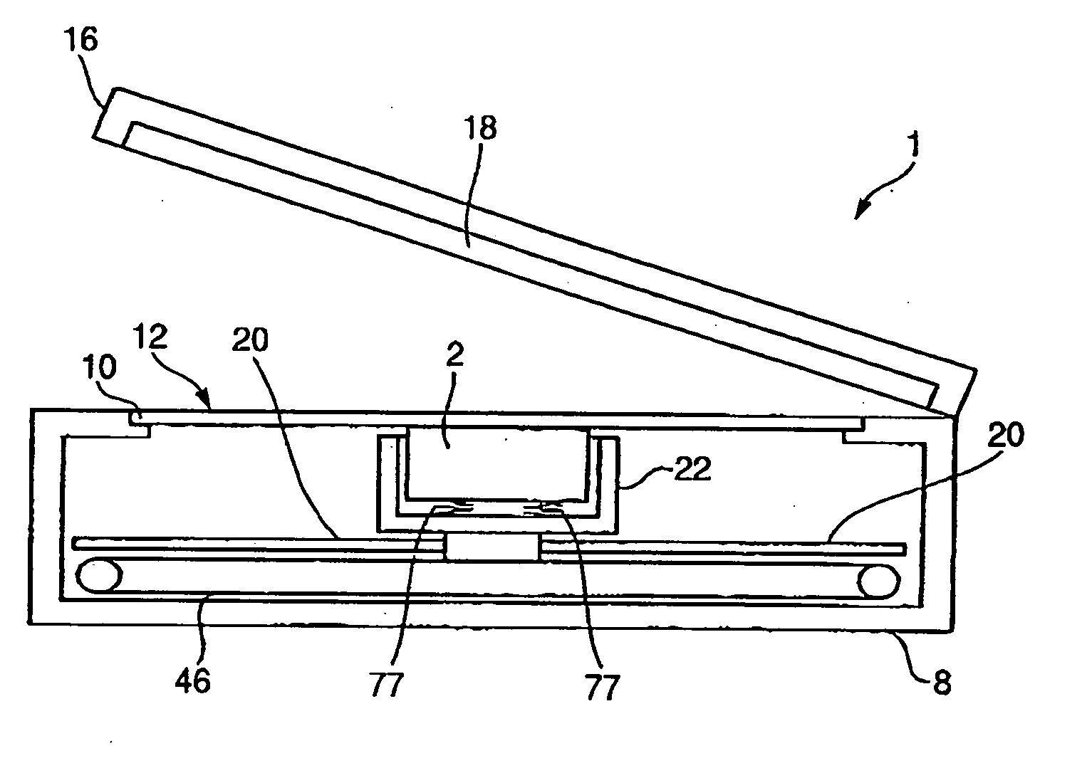
[0059] FIGS. 2 to 4B are schematic views of an image scanner 1 serving as an image reading apparatus of a first embodiment of the invention. The image scanner 1 is a so-called flat-bed type image scanner. The image scanner 1 can read a reflective document 4 (see FIG. 4A) of up to A4 size and A4 / letter size and a transmissive document. The reflective document 4 is a printed document, a photograph, or the like. The transmissive document is a 35 mm film (negative / positive) 6 (see FIG. 4B) or the like In the following description, the 35 mm film is used as the transmissive document. Additionally, the image reading apparatus may be a sheet-feed type image scanner and may also be a complex machine. Besides, the transmissive document is not limited to the 35 mm film.

[0060] A housing 8 shown in FIG. 3 is formed into an open-topped box shape. A document platen 10, formed of a substantially rectangular transparent plate such as a glass plate, closes an opening of the housing 8. The reflectiv...

second embodiment

[0099]FIG. 14A is a top view of a contact image sensor module 90 of a second embodiment, and FIGS. 14B and 14C are side views of the contact image sensor module 90 as seen from the directions X and Y, respectively, shown in FIG. 14A. In the second embodiment as well, a second linear image sensor 32 is housed in a first protruding portion 91 of a casing 99, and a first linear image sensor 30 is housed in a portion other than the first protruding portion 91. In the second embodiment, each of spacers 92 is not divided into a first spacer and a second spacer, but is formed as a single member

[0100] Similar to the first embodiment, even with the spacers 92 of the second embodiment, an adjustment can be made so that a clear image is focused both onto the first and second linear image sensors 30 and 32.

third embodiment

[0101]FIG. 15A is a top view of a contact image sensor module 95 of a third embodiment, and FIGS. 15B and 15C are side views of the contact image sensor module 95 as seen from the directions X and Y, respectively, shown in FIG. 11A. In a casing 98 of the third embodiment, a position of each end portion thereof to which a spacer 97 is attached does not protrude, and the spacers 97 are formed to have a smaller width in the sub scanning direction than in the first embodiment. Here, the direction W in the figures indicates the sub scanning direction.

[0102] Similar to the first embodiment, even with the spacers 97 of the third embodiment, an adjustment can be made so that a clear image is focused both onto the first and second linear image sensors 30 and 32.

[0103] However, the larger the width of the spacers, the larger the distance between the projections can be made, and the inclination of the virtual plane can thereby be finely adjusted. Accordingly, when the virtual plane need not ...


PUM


Abstract

A document platen supports a document. A sensor module has a first sensor reading the document and a second sensor disposed parallel to the first sensor and reading the document. An adjustment member adjusts an inclination of the sensor module to the document platen.

Description

BACKGROUND OF THE INVENTION [0001] The present invention relates to an Image reading apparatus. [0002] An image reading apparatus (see JP-A-2001-133906) mounted with a contact image sensor module has heretofore been known. Since an optical system of the contact image sensor module has a short optical path, it is easy to reduce the size of the image reading apparatus. [0003] However, since the contact image sensor module has a shallow depth field, the image reading apparatus cannot clearly read a document placed at a position away from a platen surface of a document platen. For example, an image reading apparatus described in JP-A-2001-133906 cannot clearly read a 35 mm film or the like held by a holder. [0004] Image reading apparatuses described in JP-A-2003-37712 and JP-A-2003-37713, each including a plurality of optical systems, can clearly read a reflective document and a transmissive document by changing an optical path in response to the document However, the image reading appa...

Claims


Application Information

Patent Timeline
IPC IPC(8): H04N1/04
CPCH04N1/0318H04N1/1017H04N1/193H04N2201/0456H04N2201/03141H04N2201/03145H04N2201/0315H04N2201/03112
Inventor OHARA, TOSHIMITSU
Owner SEIKO EPSON CORP
Why Eureka
Try Eureka