

Image forming device
- Summary
- Abstract
- Description
- Claims
- Application Information
AI Technical Summary
Benefits of technology
Problems solved by technology
Method used
Image

Examples
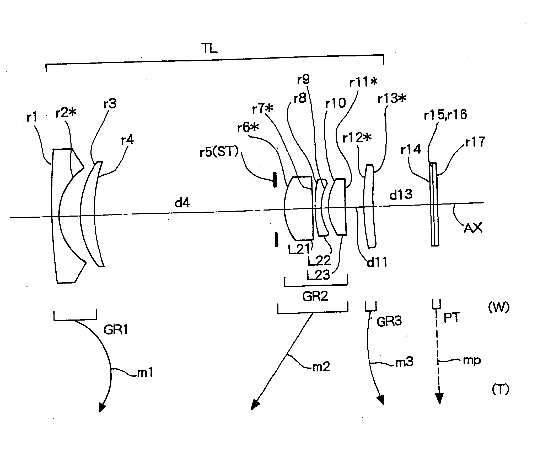
example 1
[0083]
f=5.50−9.29−15.68
FNO.=3.05−3.73−4.90
[Radius of Curvature][Axial Distance][Refractive Index(Nd)][Abbe Number(νd)]r1 = 80.640d1 = 1.000N1 = 1.76743ν1 = 49.48r2* = 5.300d2 = 2.804r3 = 10.767d3 = 1.723N2 = 1.84666ν2 = 23.78r4 = 23.023d4 = 16.761-7.087-1.498r5 = INF(ST)d5 = 1.000r6* = 6.000d6 = 3.367N3 = 1.53048ν3 = 55.72 (L21(+))r7* = 7.652d7 = 0.832r8 = 45.902d8 = 0.800N4 = 1.80518ν4 = 25.46 (L22(−))r9 = 8.401d9 = 0.005N5 = 1.51400ν5 = 42.83r10 = 8.401d10 = 1.948N6 = 1.58913ν6 = 61.25 (L23(+))r11 = −8.598d11 = 4.079-10.312-20.865r12* = 15.195d12 = 1.451N7 = 1.53048ν7 = 55.72 (GR3(+))r13* = 30.000d13 = 7.161-5.987-3.248r14 = INFd14 = 0.500N8 = 1.51680ν8 = 64.20r15 = INFd15 = 0.000r16 = INFd16 = 0.500N9 = 1.51680ν9 64.20r17 = INF[Aspherical Coefficient]r2*ε = 0.3020A4 = −0.64908782E−04A6 = 0.46698117E−05A8 = −0.42637540E−06A10 = 0.14545351E−07A12 = −0.18588005E−09r6*ε = 1.0000A4 = −0.49251260E−03A6 = −0.82311406E−05A8 = −0.51450757E−06r7*ε = 1.0000A4 = 0.29787285E−03A6 = −0.860708...
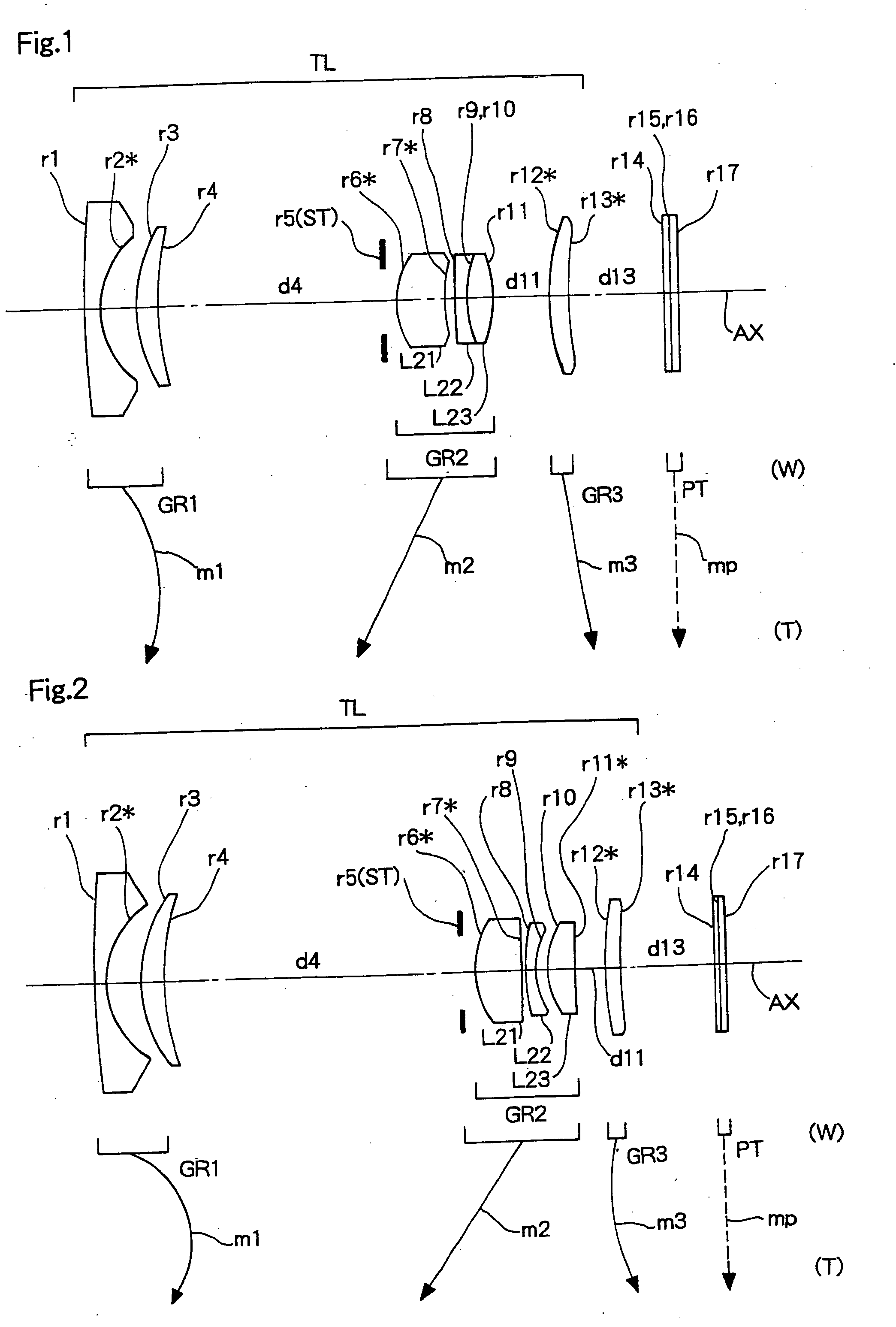
example 2
[0084]
f=5.80−9.53−21.38
FNO.=2.88−3.44−5.00
[Radius of Curvature][Axial Distance][Refractive Index(Nd)][Abbe Number(νd)]r1 = 67.905d1 = 1.000N1 = 1.76743ν1 = 49.48r2* = 6.433d2 = 3.141r3 = 11.824d3 = 1.796N2 = 1.84666ν2 = 23.78r4 = 22.284d4 = 25.605-12.044-1.680r5 = INF(ST)d5 = 1.000r6* = 6.093d6 = 4.071N3 = 1.53048ν3 = 55.72 (L21(+))r7* = 50.000d7 = 0.360r8 = 20.955d8 = 0.800N4 = 1.80518ν4 = 25.46 (L22(−))r9 = 5.916d9 = 1.107r10 = 7.246d10 = 2.325N5 = 1.53048ν5 = 55.72 (L23(+))r11* = −71.675d11 = 2.500-5.347-22.792r12* = 22.312d12 = 1.447N6 = 1.53048ν6 = 55.72 (GR3(+))r13* = 72.018d13 = 8.074-9.180-5.470r14 = INFd14 = 0.500N7 = 1.51680ν7 = 64.20r15 = INFd15 = 0.000r16 = INFd16 = 0.500N8 = 1.51680ν8 = 64.20r17 = INF[Aspherical Coefficient]r2*ε = 0.2912A4 = 0.37573117E−04A6 = 0.62712310E−06A8 = −0.33626912E−07A10 = 0.83547899E−09A12 = −0.81452832E−11r6*ε = 1.0000A4 = −0.38219846E−03A6 = −0.79507576E−05A8 = −0.41873850E−06r7*ε = 1.0000A4 = −0.40552524E−03A6 = −0.18911411E−04A8 = 0.3483...
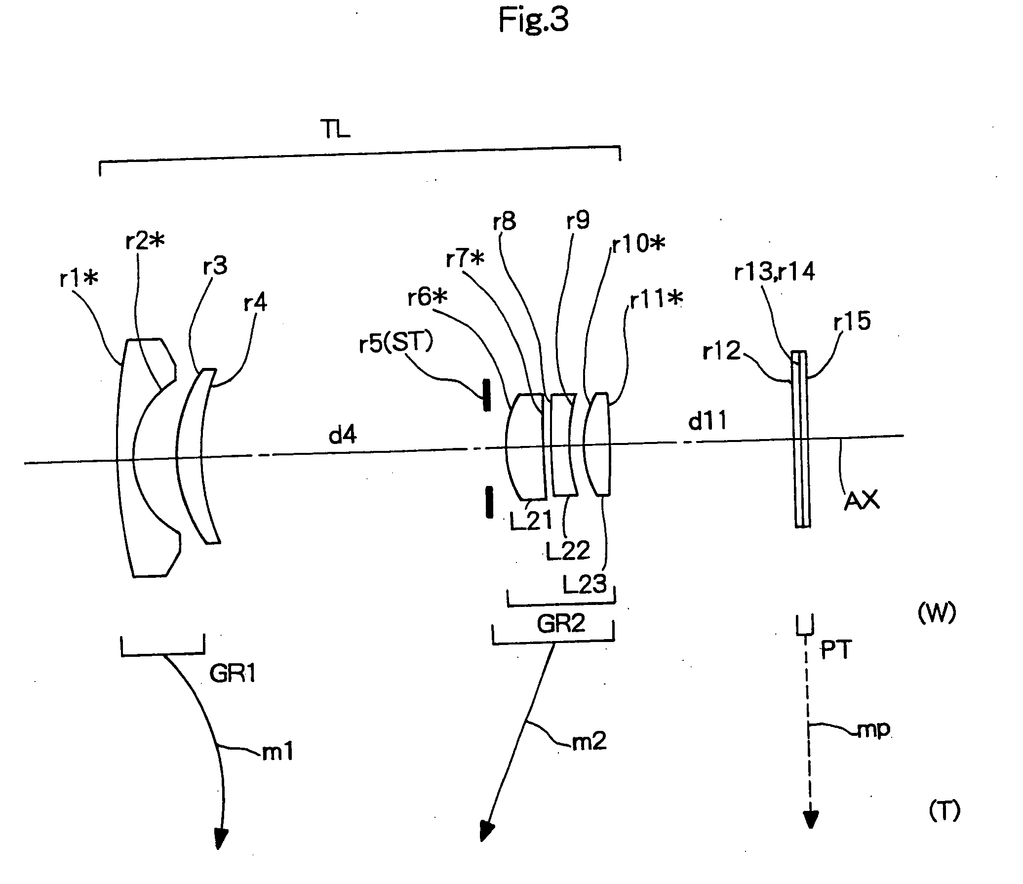
example 3
[0085]
f=5.54−9.35−15.79
FNO.=3.30−3.89−4.90
[0086]
[Radius of Curvature][Axial Distance][Refractive Index(Nd)][Abbe Number(νd)]r1* = 72.995d1 = 1.000N1 = 1.76743ν1 = 49.48r2* = 5.300d2 = 2.832r3 = 9.000d3 = 1.737N2 = 1.84666ν2 = 23.78r4 = 14.852d4 = 19.090-8.228-1.791r5 = INF(ST)d5 = 1.000r6* = 6.000d6 = 2.422N3 = 1.53048ν3 = 55.72 (L21(+))r7* = 20.000d7 = 0.574r8 = 49.627d8 = 1.200N4 = 1.84666ν4 = 23.78 (L22(−))r9 = 10.000d9 = 1.000r10* = 8.676d10 = 1.797N5 = 1.48749ν5 = 70.44 (L23(+))r11* = −13.433d11 = 12.277-16.133-22.644r12 = INFd12 = 0.500N6 = 1.51680ν6 = 64.20r13 = INFd13 = 0.000r14 = INFd14 = 0.500N7 = 1.51680ν7 = 64.20r15 = INF[Aspherical Coefficient]r1*ε = 1.0000A4 = 0.48597091E−03A6 = −0.17926702E−04A8 = 0.29793659E−06A10 = −0.24929599E−08A12 = 0.13042277E−10r2*ε = 0.7167A4 = 0.43141973E−03A6 = −0.16407899E−04A8 = −0.73786990E−06A10 = 0.16896544E−07A12 = −0.10290956E−09r6*ε = 1.0000A4 = −0.49852456E−03A6 = 0.63781505E−06A8 = −0.32900976E−05A10 = −0.20332202E−06A12 = 0.15824...
PUM
 Abstract
Description
Claims
Application Information