
Tactile warning system

a tactile warning and warning system technology, applied in the field of tactile warning systems, can solve the problems of previously developed tactile warning systems, the danger of sight impaired individuals, and the inability to detect the presence of objects,

Inactive Publication Date: 2006-02-02
HOTTAPE ACQUISITION LLC
View PDF18 Cites 28 Cited by
  • Summary
  • Abstract
  • Description
  • Claims
  • Application Information

AI Technical Summary

Benefits of technology

"The present invention relates to a tactile warning system that can be applied to an application surface to provide tactile warning sensations to a user. The system includes a top layer with a plurality of tactile warning members attached thereto, which can be heated to a selected temperature to at least partially molten, resulting in the covering of the tactile warning members and adhering of the top layer to the application surface, sandwiching the tactile warning members between the top layer and the application surface. The system can be applied without the use of an adhesive or other intermediate layer. The tactile warning members can be formed from a heat resistant material, such as ceramic, and can be adhered to the top layer prior to installation. The system can also include a sheet formed from an activatable material that can adhere to the application surface without an adhesive, sandwiching the tactile warning members between the sheet and the application surface. The method of applying the system involves placing the sheet and the tactile warning members on the application surface and activating the sheet to adhere it to the application surface sandwiching the tactile warning members between the application surface and the sheet."

Problems solved by technology

However, it has been found that transitions, which provide means for transitioning between safe pedestrian paths and obstacles and / or hazards, a few examples of transitions being curb ramps, vehicle drop-offs, and depressed corners providing means for transitioning between an elevated surface and a lower surface, although accommodating access to wheelchair bound individuals and others, provide a hazard to sight impaired individuals.
Therefore, a sight impaired individual may accidentally walk onto / into the obstacle or hazard, such as a roadway, since there is no raised curb to mark and separate the safe pedestrian route when there is a ramp providing a gradual transition from the elevated surface to the lower surface.
Although somewhat effective, these previously developed tactile warning systems are not without their problems.
The thermoplastic tactile warning system cannot be heated by the propane heat gun since the truncated domes would melt and spread out, thus losing their shape.
Although effective, this system is not without its problems.
First, the thermoplastic material, even when properly applied by adhesives, has been found susceptible to delaminating due to adhesive failure, thereby presenting a tripping hazard.
This process is cumbersome, prone to error, especially in the accurate placement of the sheet upon the adhesive layer.
When the sheet is not perfectly placed on the adhesive, two problems occur.
First, some of the adhesive is exposed, producing an unsightly installation and causing a tripping hazard.
Second, a portion of the sheet may not be in contact with the adhesive layer, permitting an edge of the sheet to roll up or catch a pedestrian's foot, creating a tripping hazard.
Further, it has been found that the above described tactile warning system does not conform well to the surface it is applied to, leading to air pockets and / or permitting water and ice to make its way under the tactile warning system, leading to its deterioration and / or delamination and creating an unaesthetic appearance.
Further, the two layers (i.e., the sheet and the adhesive layer) increase the overall height of the tactile warning system, increasing the tripping hazard of the installation.
The tactile warning systems utilizing liquid adhesives encounter the same problems mentioned above.
Further, the adhesive application process these systems utilize is messy, labor intensive, and results in the release of volatile organic compounds (VOCs) to the atmosphere, and often requires more extensive surface preparation than for the heat activated adhesive layer systems described above.

Method used


Image

  • Tactile warning system
  • Tactile warning system
  • Tactile warning system

Examples


Embodiment Construction

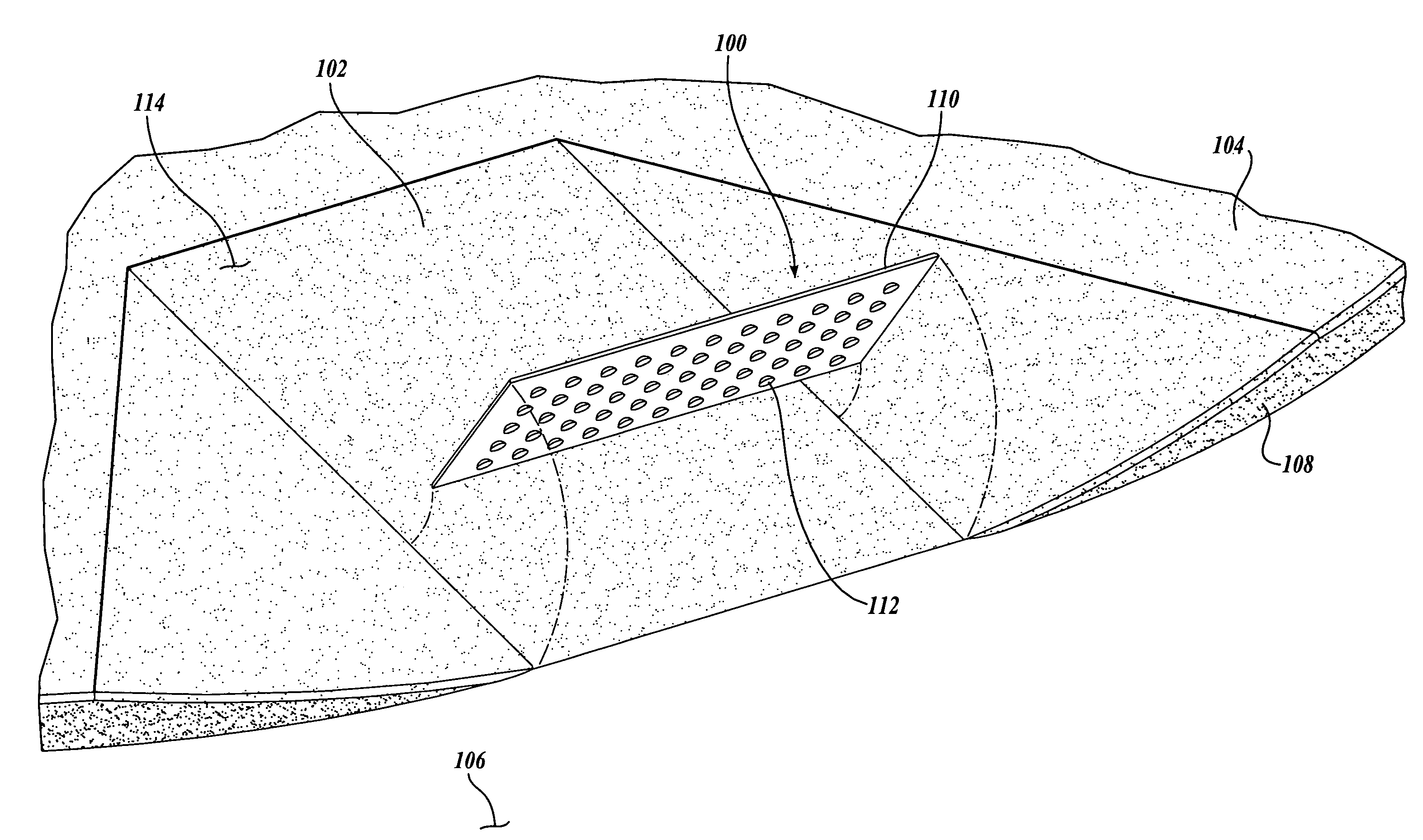
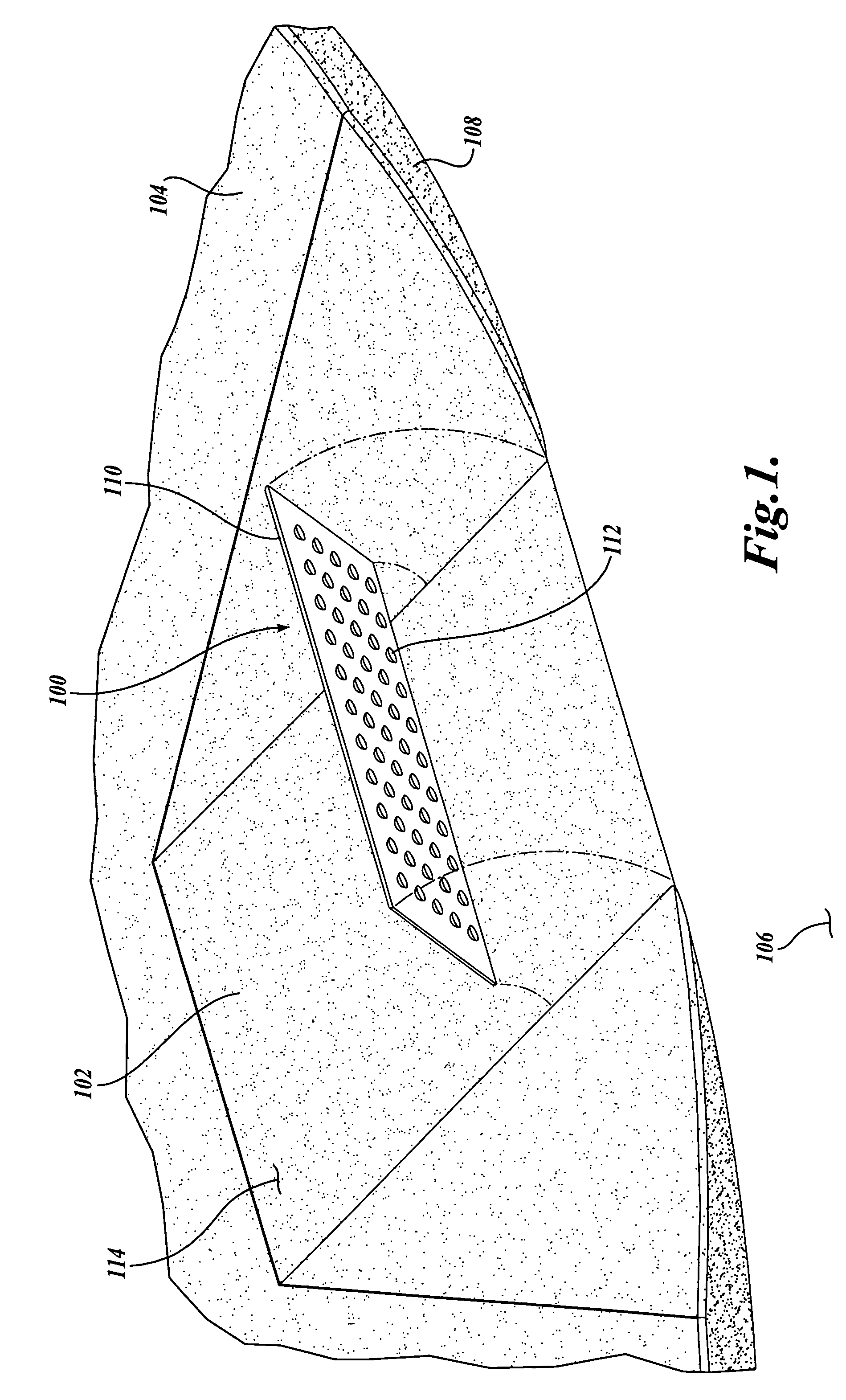
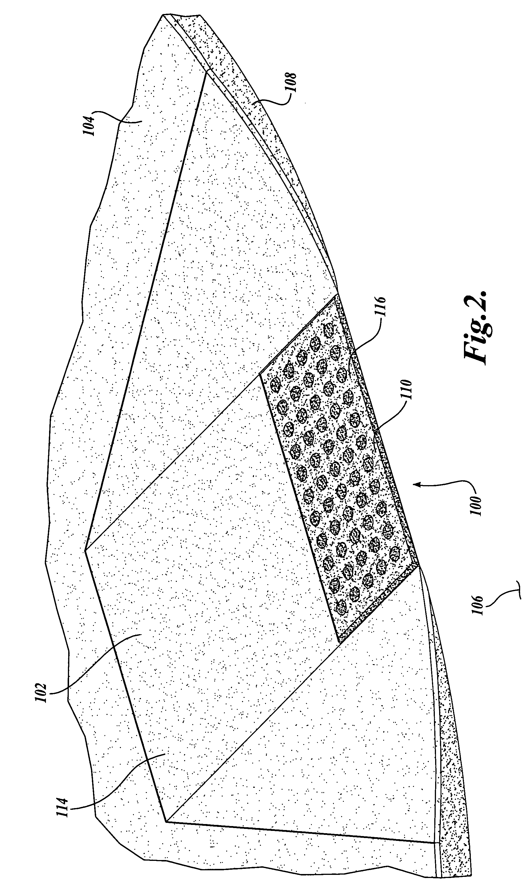
[0025] Referring to FIGS. 1-5, one embodiment of a tactile warning system 100 formed in accordance with the present invention is disclosed. Turning to FIG. 2, the tactile warning system 100 provides a textural change to warn sight impaired individuals of a hazard or obstacle in the vicinity of the sight impaired individual. Moreover, the tactile warning system 100 provides a contrasting texture that signals a potentially hazardous condition to the pedestrian, and thereby informs the pedestrian to exercise care.

[0026] In the illustrated embodiment, the tactile warning system 100 is shown as applied to a ramp 102 of a sidewalk 104. Normally, the raised height of the sidewalk 104 relative to the height of the adjacent roadway 106 provides a curb edge 108 which indicates to a sight impaired individual the presence of the roadway 106. However, it has been found that transitions, such as curb ramps 102, vehicle drop-offs, depressed corners, and the like, although accommodating access to ...


PUM


Abstract

A tactile warning system (100 or 200) having an application surface (114 or 214) and a sheet (110 or 210) formed from a predetermined material and adhered to the application surface. The tactile warning system includes a plurality of tactile warning members (112 or 212) formed from a selected material different from the predetermined material of the sheet. The plurality of tactile warning members are disposed between the sheet and the application surface. The plurality of tactile warning members contact the application surface without an intermediate layer disposed therebetween.

Description

CROSS-REFERENCE TO RELATED APPLICATION [0001] This application hereby claims the benefit of U.S. Provisional Patent Application No. 60 / 598,250, filed on Aug. 2, 2004, entitled Tactile Warning System, the disclosure of which is hereby expressly incorporated by reference, and the priority from the filing date of which is hereby claimed under 35 U.S.C. § 119(e).FIELD OF THE INVENTION [0002] The present invention relates generally to tactile warning systems for indicating to sight impaired individuals the presence of a hazard and / or an obstacle. BACKGROUND OF THE INVENTION [0003] It is well known that persons with little or no usable vision depend upon environmental cues for safe and independent travel. A few examples of environmental cues are ambient sounds, buzzers, physical elements that may be sensed by a cane, such as a curb, and surface / floor texture changes that may be felt by a person's foot or cane. For instance, a sight impaired individual may use the edge of a curb of a raise...

Claims


Application Information

Patent Timeline
Patent Type & Authority Applications(United States)
IPC IPC(8): E01F11/00
CPCE01C11/222A61H3/066
Inventor SEMAN, TODD J.
Owner HOTTAPE ACQUISITION LLC
Learn More