Zero acoustic splice fan case liner

a fan case and acoustic splicing technology, applied in the field of fan cases, can solve the problems of affecting the acoustic affecting the performance of the liner assembly, so as to achieve the effect of improving the noise attenuation performan

Active Publication Date: 2006-02-02
RTX CORP
View PDF13 Cites 19 Cited by
  • Summary
  • Abstract
  • Description
  • Claims
  • Application Information

AI Technical Summary

Benefits of technology

[0006] This invention is a fan case liner assembly that includes an acoustically active joint to improve noise attenuation performance.

Problems solved by technology

Conventional seams included adhesive that fill one or two rows of chambers on each side of the seam that can result in an undesirable acoustically dead zone.
Overlapping the first and second ends, along with filling of the seam with adhesive results in a strip of blocked openings.
Blocking of the openings results in an acoustically dead area the size of the overlapped region that degrades acoustic performance of the liner assembly.

Method used


Image

  • Zero acoustic splice fan case liner
  • Zero acoustic splice fan case liner
  • Zero acoustic splice fan case liner

Examples


Embodiment Construction

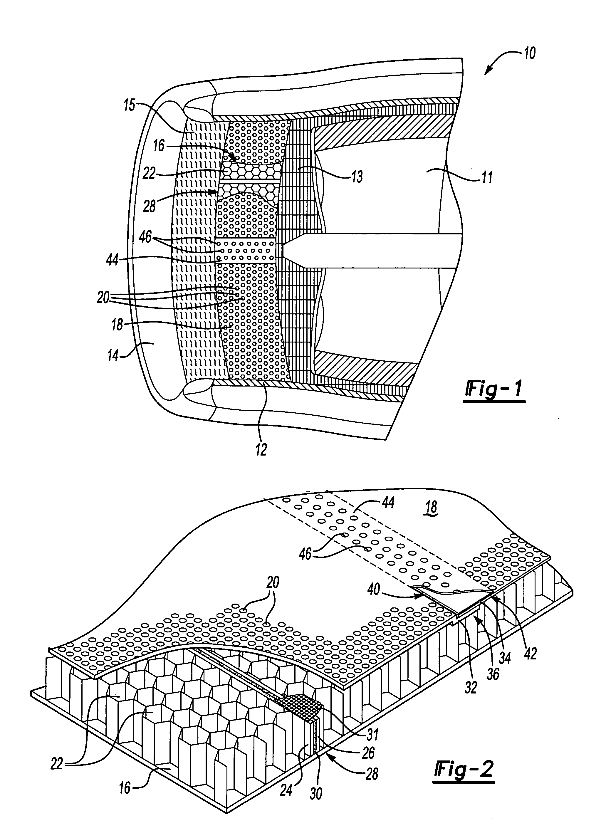
[0015] Referring to FIG. 1, a fan case 10 for a turbine engine includes a liner assembly 12, a liner strip 15 and a leading edge 14. The leading edge 14 guides airflow into and around the fan case 10. The liner strip 15 is provided between the liner assembly 12 and leading edge 14 and may also include noise attenuation features. The liner strip 15 can include other structures known by a worker versed in the art.

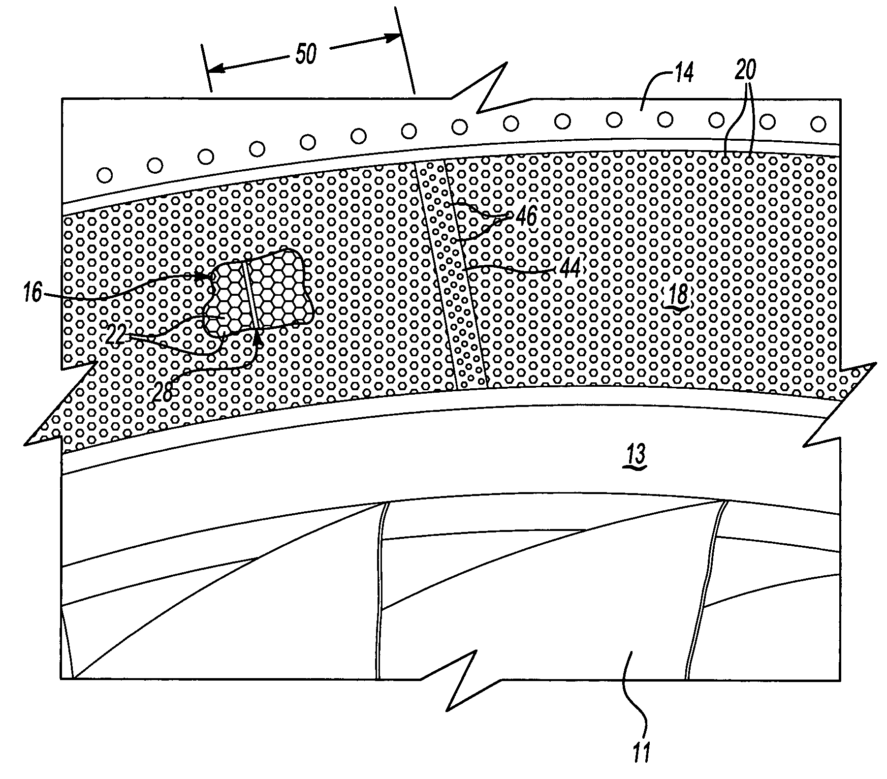
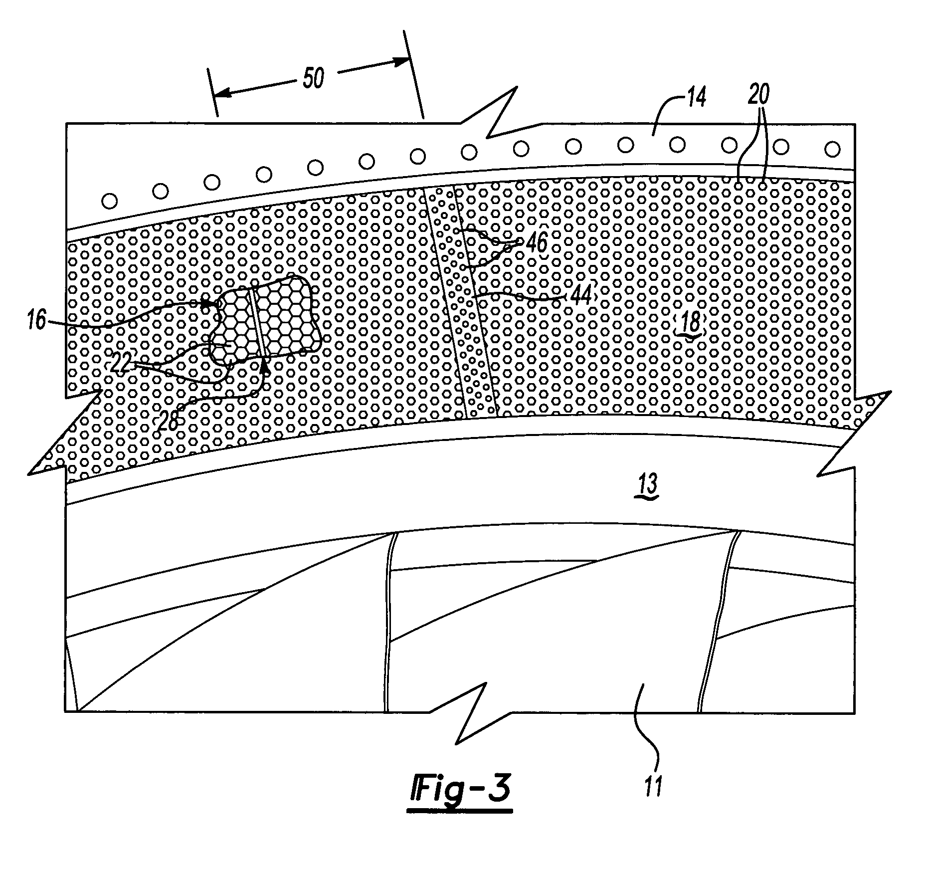
[0016] The liner assembly 12 forms an inner surface of the fan case 10 forward of a rub liner 13 and turbine blades 11. The liner assembly 12 includes a noise attenuation layer 16 covered by a face sheet 18. The face sheet 18 includes a first plurality of openings 20 that provide communication to the noise attenuation layer 16. The noise attenuation layer 16 includes a plurality of chambers 22 that each are in communication with at least one of the first plurality of openings 20. Acoustical energy generated by the engine enters the chambers 22 and is transformed into heat. T...


PUM

PropertyMeasurementUnit
sound energyaaaaaaaaaa
circumferential distanceaaaaaaaaaa
noise attenuationaaaaaaaaaa

Abstract

A liner assembly for a fan case includes a noise attenuation layer covered by a face sheet. The face sheet includes openings to the underlying noise attenuation layer. The face sheet and noise attenuation layer include acoustically transparent joints. The noise attenuation layer includes a first side joined to a second side at a seam by an adhesive strip. The adhesive strip bonds the first side to the second side without filling any chambers. The face sheet includes a joint filled with an adhesive providing the desired uninterrupted surface within the fan case. Openings are formed through the joint and the adhesive to communicate with the underlying noise attenuation layer. The joint and seam become essentially transparent acoustically to improve noise attenuation performance.

Description

BACKGROUND OF THE INVENTION [0001] This invention generally relates to a fan case for turbine engines, and more particularly to a fan case liner including an acoustically active joint. [0002] Conventional turbine and turbofan engines for aircraft include a plurality of turbine blades that rotate within a fan case. The fan case serves as a protective covering to protect the turbine blades and the aircraft. Further the fan case channels airflow into the turbine engine. The inner surface of the fan case is constructed to withstand impacts from objects that may come into contact with the fan case. Further, the inner surface of the fan case includes acoustical features to reduce the noise emitted from the engine. [0003] Restrictions on the amount of noise emitted from a turbine engine are becoming stricter. Accordingly, increased efforts are underway to further reduce the noise emitted from an aircraft engine. It is known to provide a fan case liner with a layer of noise attenuation stru...

Claims


Application Information

Patent Timeline
Patent Type & Authority Applications(United States)
IPC IPC(8): F01D11/00F02C7/045F02K1/82
CPCB64D33/02B64D2033/0206B64D2033/0286F02C7/045F02K1/827F05D2230/23Y10T29/49995F05D2260/96Y02T50/672Y10T29/49885Y10T29/49826Y10T29/49996F05D2240/14Y02T50/60
Inventor COSTA, MARK W.BROWN, CHARLESFOOSE, ANDREW S.
Owner RTX CORP
Why Eureka
Try Eureka