EMB (Electro-Mechanical Braking) control system of electric automobile and control method thereof

A control system and electric vehicle technology, applied in electric vehicles, electric braking systems, vehicle components, etc., can solve problems such as slow braking response, achieve good noise attenuation performance, avoid difficult measurement, and reduce sensitivity

Active Publication Date: 2017-03-08
SICHUAN VOCATIONAL COLLEGE OF SICHUAN
View PDF8 Cites 4 Cited by
  • Summary
  • Abstract
  • Description
  • Claims
  • Application Information

AI Technical Summary

Problems solved by technology

[0010] The invention provides an EMB control system for an electric vehicle, aiming to solve the problem that the traditional braking system mostly adopts a hybrid braking method of gas, hydraulic and mechanical, and the braking response is slow

Method used


Image

  • EMB (Electro-Mechanical Braking) control system of electric automobile and control method thereof
  • EMB (Electro-Mechanical Braking) control system of electric automobile and control method thereof
  • EMB (Electro-Mechanical Braking) control system of electric automobile and control method thereof

Examples


Embodiment 1

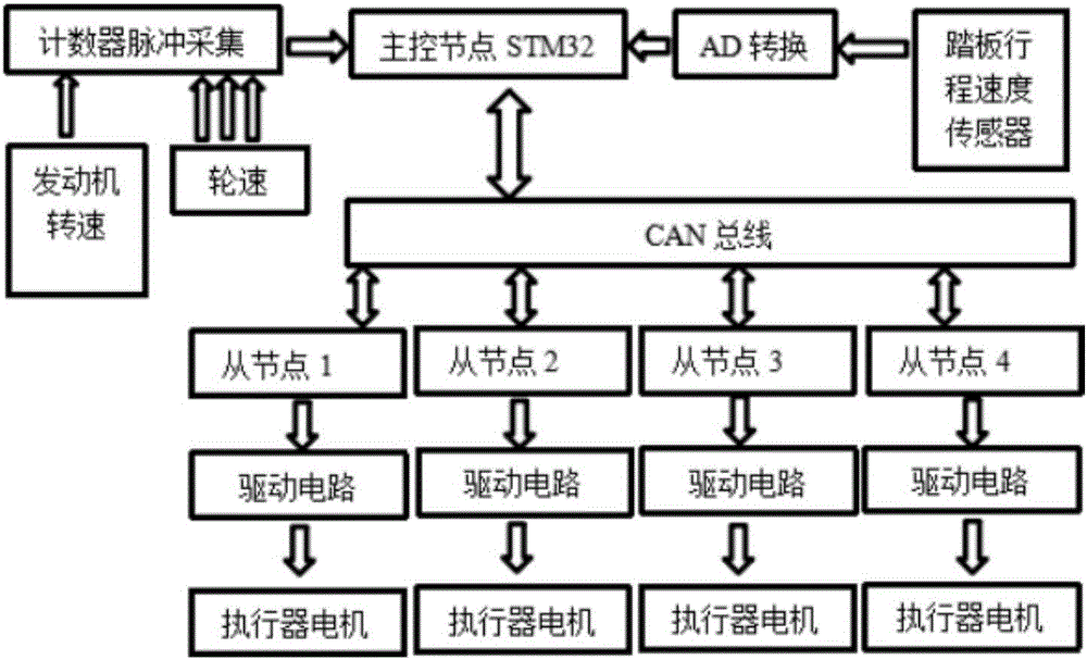
[0080] refer to figure 1 , figure 2 and image 3 , an EMB control system for an electric vehicle, comprising a CAN bus, a primary node control system and four secondary node control systems, the four secondary node control systems are respectively used to control the braking of four wheels.

[0081] The first-level node control system includes an electronic brake pedal, a signal acquisition module, an AD converter, a first-level microcontroller and a first-level CAN bus transceiver.

[0082] The signal acquisition module includes a counter stamping acquisition unit, a displacement sensor and a speed sensor. The counter stamping acquisition unit is used to acquire the rotational speed of the engine and the wheel speed of the wheels. The displacement sensor is used to collect the travel signal of the electronic brake pedal; the speed sensor is used to collect the stepping speed signal of the electronic brake pedal.

[0083] The signal acquisition module transmits the collecte...

Embodiment 2

[0089] On the basis of embodiment one, embodiment two further optimizes and limits the content in embodiment one:

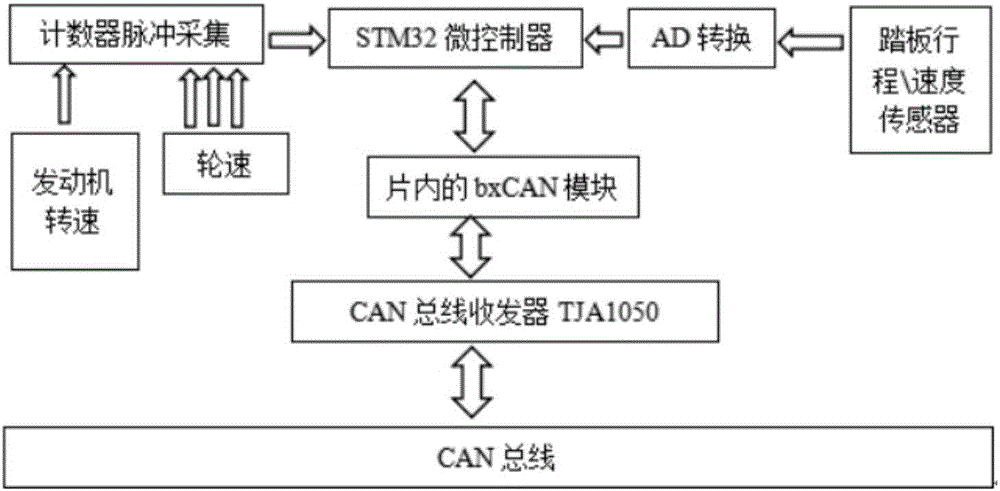
[0090] Both the first-level microcontroller and the second-level microcontroller use the STM32 microcontroller, and the first-level microcontroller and the second-level microcontroller use the STM32F103 embedded chip integrated with the bxCAN controller. The circuit structure of the STM32 chip refers to Figure 4 .

[0091] refer to Figure 5 , CAN bus architecture is mainly divided into three layers: application layer, data link layer and physical layer. Among them, the physical layer is the circuit that realizes the connection between ECU (vehicle single-chip microcomputer, electronic control unit) and the bus, and the total number of ECUs depends on the power load of the bus.

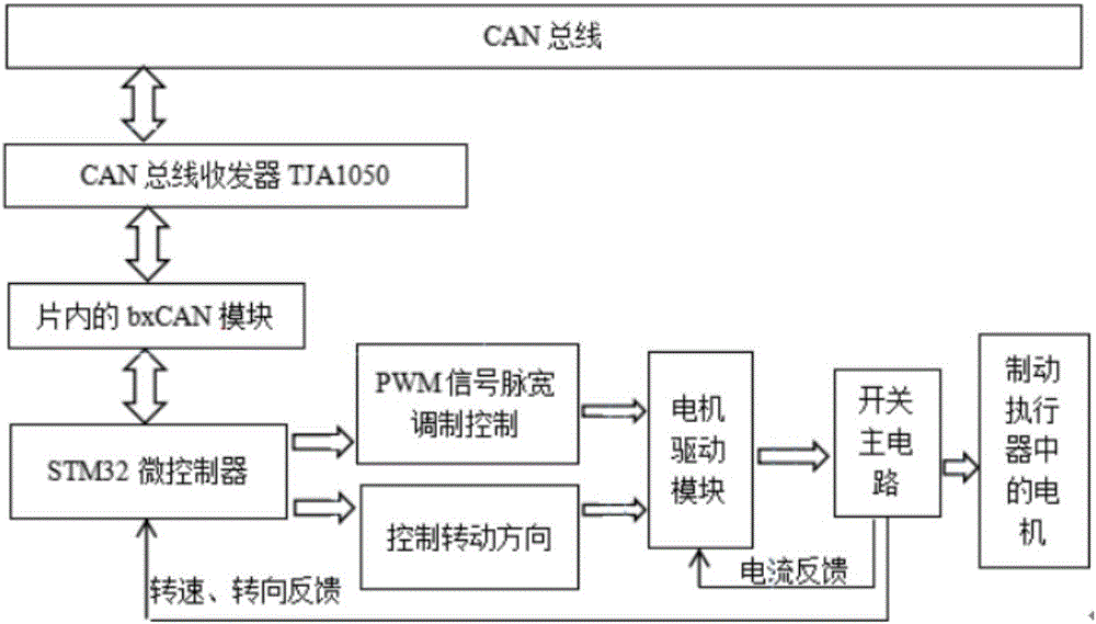
[0092] The CAN bus interface circuit design is mainly designed for the physical layer, and its controller mainly realizes the work of the data link layer in the CAN bus protocol. Sinc...

Embodiment 3

[0097] On the basis of the above-mentioned embodiments, the third embodiment further optimizes and limits the content in the above-mentioned embodiments:

[0098] refer to Figure 6 , the counter modulus acquisition unit includes a magnetoelectric sensor, an optical isolator and a voltage comparator; the optical isolator converts the wheel speed electrical signal collected by the magnetoelectric sensor into an optical signal, and the optical signal is converted into a pulse signal through the voltage comparator; The stage node control system also includes a potentiometer connected to the inverting input terminal of the voltage comparator.

[0099] In the process of sampling the wheel speed, the output signal must be conditioned by the magnetic sensor. The conditioning circuit is mainly used to adjust the sinusoidal signal output by the magnetoelectric sensor to an external counting pulse that can be recognized by STM32, and the electrical signal is converted into an optical s...


PUM


Abstract

The invention provides an EMB (Electro-Mechanical Braking) control system of an electric automobile and a control method thereof, and aims to solve the problem of slow braking response of most conventional braking systems which adopt a gas, liquid and mechanical composite braking mode. The EMB control system of the electric automobile comprises a CAN (Controller Area Network) bus, a first-stage node control system and four second-stage node control systems, wherein the four second-stage node control systems are used for controlling braking of four wheels respectively. The first-stage node control system comprises an electronic brake pedal, a signal acquisition module, a first-stage microcontroller and a first-stage CAN bus transceiver. Each second-stage node control system comprises a second-stage CAN bus transceiver, a second-stage microcontroller, a driving unit and an actuator motor; and the second-stage CAN bus transceiver receives a control signal sent by the first-stage CAN bus transceiver by virtue of the CAN bus. By adopting the EMB control system and the control method provided by the invention, an electric driving system is good in controllability and high in response speed, and the active safety performance of an automobile can be obviously improved.

Description

technical field [0001] The invention relates to an intelligent braking system for an electric vehicle, in particular to an EMB control system and a control method for the electric vehicle. Background technique [0002] At present, the improvement of automobile safety is mainly solved by active and passive safety technologies. Passive safety technologies aim to reduce injuries. The core of active safety technology is prevention. When the vehicle is in an unstable state, it will control the stability of the vehicle; rough or smooth ground), and can operate according to the driver's intention. Therefore, the development of active safety technology has been paid more and more attention. [0003] At present, automotive active safety technologies mainly include visual enhancement system, distance warning system, PRE-SAFE safety protection system, anti-lock braking system (ABS), departure warning system, vehicle stability control system (ESP), electronic braking force distributi...

Claims


Application Information

Patent Timeline
Patent Type & Authority Applications(China)
IPC IPC(8): B60L7/26
CPCB60L7/26B60L2260/44
Inventor 罗茂元陈天伟
Owner SICHUAN VOCATIONAL COLLEGE OF SICHUAN
Why Eureka
Try Eureka