Fuel cell stack

a fuel cell and stack technology, applied in the field of fuel cell stacks, can solve the problems of large number of components of the unit cell, undetectable electrical corrosion in the metal plate, easy flow of corrosion current through the metal plate, etc., and achieve the effect of simple and economical structur

Inactive Publication Date: 2006-02-02
HONDA MOTOR CO LTD
View PDF7 Cites 33 Cited by
  • Summary
  • Abstract
  • Description
  • Claims
  • Application Information

AI Technical Summary

Benefits of technology

[0010] A main object of the present invention is to provide a fuel cell stack having a simple and economical structure in which terminal plates are insulated suitably.

Problems solved by technology

Therefore, corrosion current flows through the metal plates easily, and electrical corrosion may occur in the metal plates undesirably.
Therefore, the number of components of the unit cell is large, and the unit cell cannot be produced economically.

Method used


Image

  • Fuel cell stack
  • Fuel cell stack
  • Fuel cell stack

Examples


Embodiment Construction

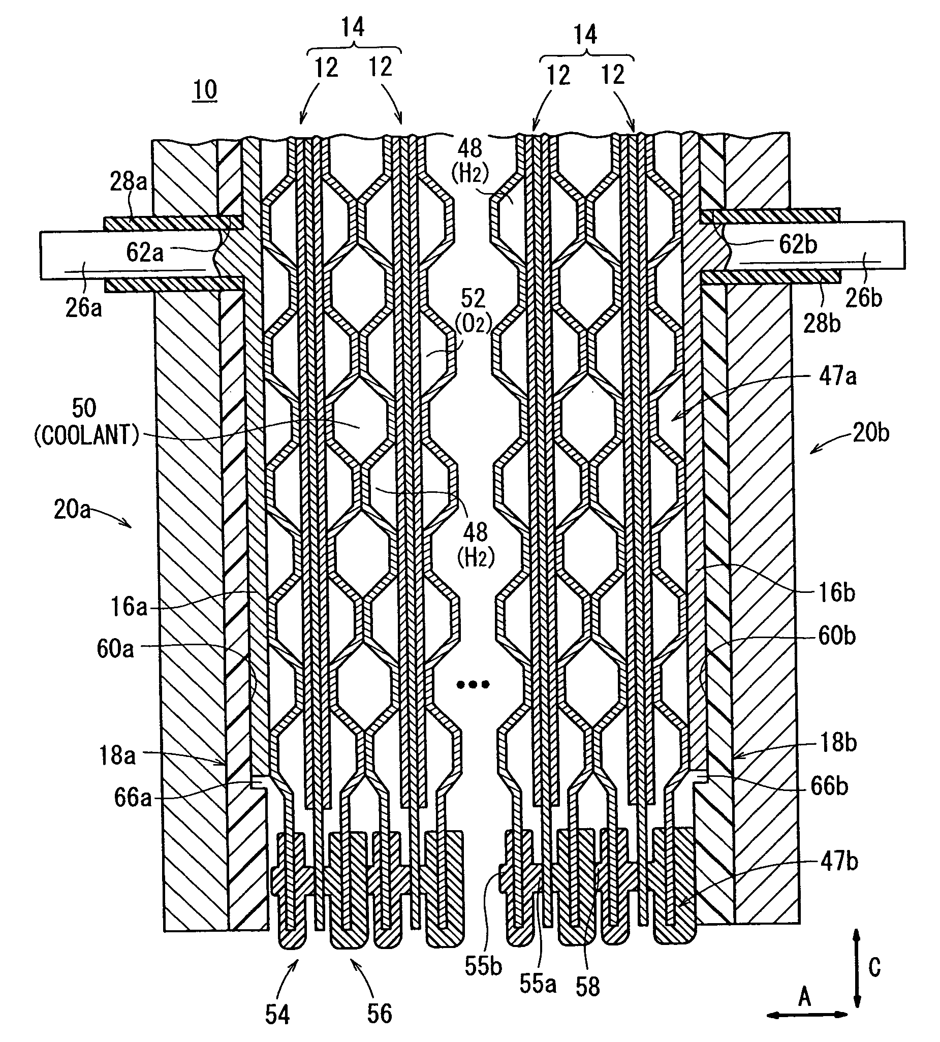
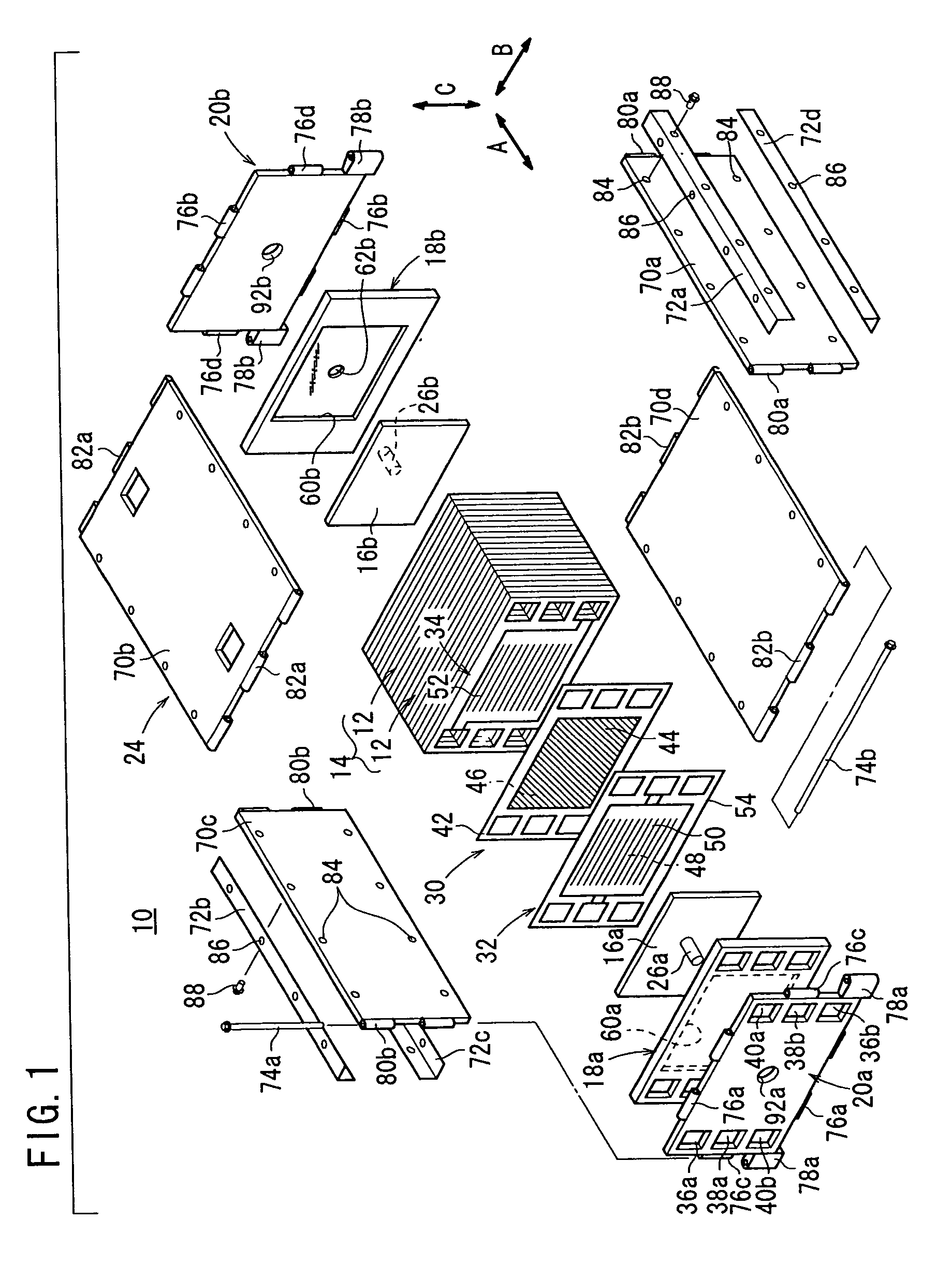
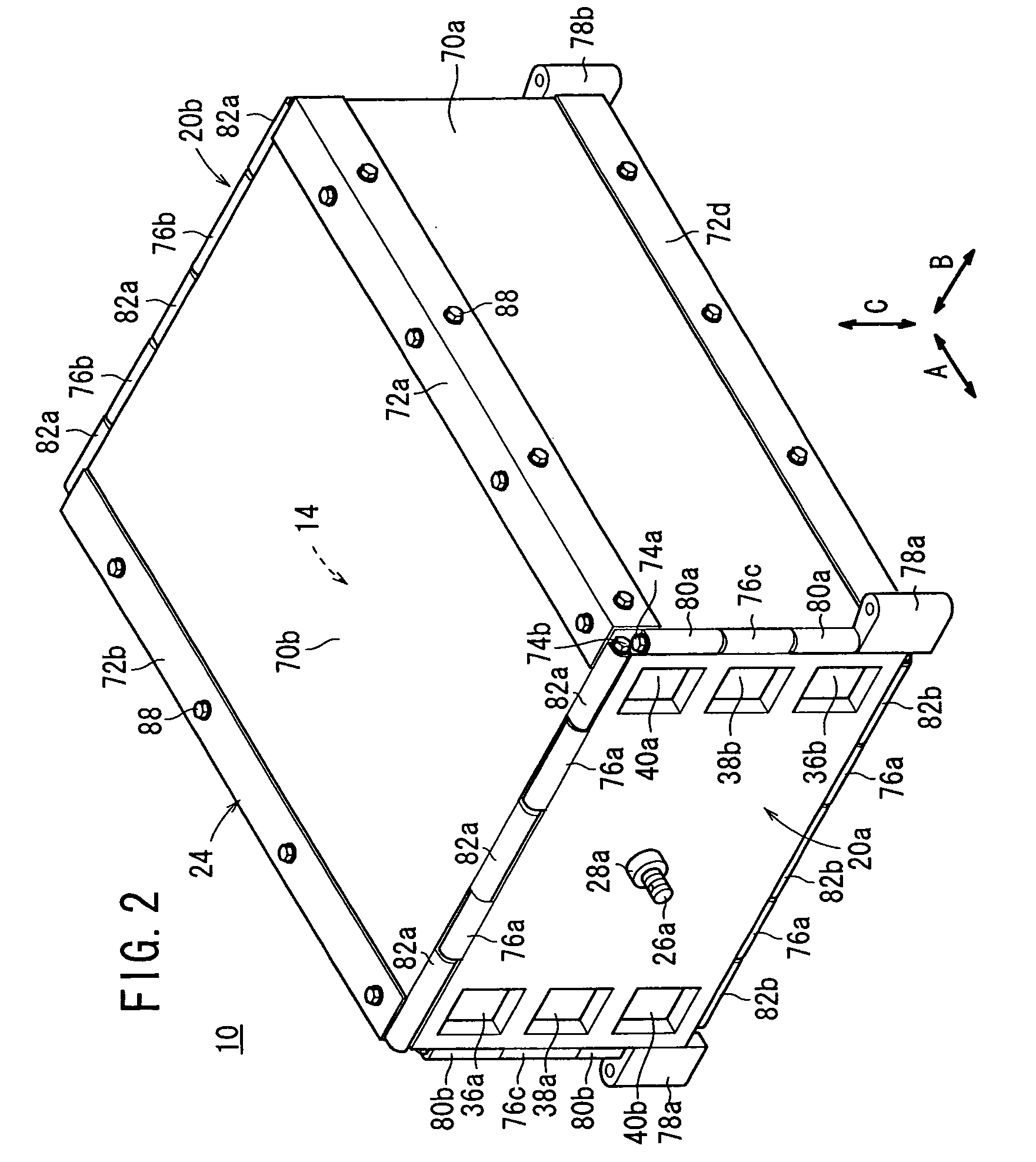
[0023]FIG. 1 is a partial exploded perspective view schematically showing a fuel cell stack 10 according to an embodiment of the present invention. FIG. 2 is a perspective view schematically showing the fuel cell stack 10. FIG. 3 is a partial cross sectional side view showing the fuel cell stack 10.

[0024] As shown in FIG. 1, the fuel cell stack 10 includes a stack body 14 formed by stacking a plurality of unit cells 12 horizontally in a stacking direction indicated by an arrow A. At one end of the stack body 14 in the stacking direction indicated by the arrow A, a terminal plates 16a is provided. An insulating plate (insulating member) 18a is provided outside the terminal plate 16a. Further, an end plate 20a is provided outside the insulating plate 18a.

[0025] At the other end of the stack body 14 in the stacking direction, a terminal plate 16b is provided. An insulating plate (insulating member) 18b is provided outside the terminal plate 16b. Further, an end plate 20b is provided ...


PUM

PropertyMeasurementUnit
chemicalaaaaaaaaaa
DC electrical energyaaaaaaaaaa
corrosionaaaaaaaaaa

Abstract

A terminal plate, an insulating plate, and an end plate are stacked together. A rectangular recess is formed at the center of the insulating plate. The terminal plate is placed in the recess. An oxygen-containing gas supply passage, a coolant supply passage, a fuel gas discharge passage, a fuel gas supply passage, a coolant discharge passage, and an oxygen-containing gas discharge passage as fluid passages extend through the insulating plate. These fluid passages do not extend through the terminal plate.

Description

BACKGROUND OF THE INVENTION [0001] 1. Field of the Invention [0002] The present invention relates to a fuel cell stack comprising a plurality of unit cells stacked together in a stacking direction, and terminal plates, insulating members, and end plates provided at opposite ends of the unit cells in the stacking direction. Each of the unit cells includes an electrolyte electrode assembly and a pair of separators sandwiching the electrolyte electrode assembly. The electrolyte electrode assembly includes a pair of electrodes, and an electrolyte interposed between the electrodes. [0003] 2. Description of the Related Art [0004] For example, a solid polymer fuel cell employs a membrane electrode assembly which includes an anode and a cathode each having a catalyst and porous carbon particles, and an electrolyte membrane (electrolyte) interposed between the anode and the cathode. The electrolyte membrane is a polymer ion exchange membrane. The membrane electrode assembly and separators (b...

Claims


Application Information

Patent Timeline
Patent Type & Authority Applications(United States)
IPC IPC(8): H01M8/24H01M8/02H01M8/04
CPCH01M8/0273Y02E60/50H01M8/242H01M8/2483H01M8/0267
Inventor SATO, MASAHIKOGOTO, SHUHEINISHIYAMA, TADASHI
Owner HONDA MOTOR CO LTD
Why Eureka
Try Eureka