Dual damascene diffusion barrier/liner process with selective via-to-trench-bottom recess

Inactive Publication Date: 2006-02-02
TEXAS INSTR INC
View PDF8 Cites 126 Cited by
  • Summary
  • Abstract
  • Description
  • Claims
  • Application Information

AI Technical Summary

Benefits of technology

[0007] An advantage of the invention is providing an improved diffusion barrier/liner layer.
[0008] This and other advantages

Problems solved by technology

Unfortunately, suitable copper etches for a semiconductor fabrication environment are not readily available.
Unfortunately, physical vapor deposition (PVD) processes typically used to deposit the liner/barrier and seed materials have poor step coverage.
The overhang causes a severe problem during the subsequent copper ECD.
Unfortunately, the s

Method used


Image

  • Dual damascene diffusion barrier/liner process with selective via-to-trench-bottom recess
  • Dual damascene diffusion barrier/liner process with selective via-to-trench-bottom recess
  • Dual damascene diffusion barrier/liner process with selective via-to-trench-bottom recess

Examples


Example

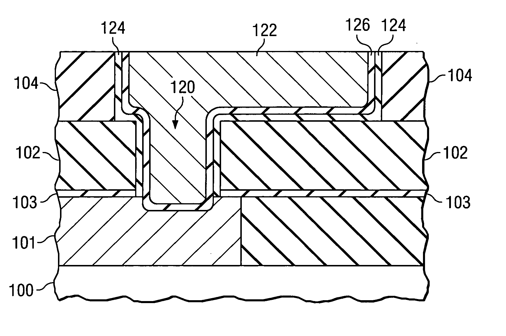
[0012] The invention will now be discussed with reference to diffusion barrier / liner for a copper dual damascene process. It will be apparent to those of ordinary skill in the art that the invention may be applied to other liner layers and methods for selectively removing such layers different portions of a feature such as a trench / via feature.

[0013] An interconnect structure formed according to an embodiment of the invention is shown in FIG. 1. A via structure 120 extends through an interlevel dielectric (ILD) 102 and connects between a lower copper interconnect 101 and an upper copper interconnect (trench structure 122). Trench structure 122 and via structure 120 comprise a first barrier / liner 124. First barrier liner 124 lines the sidewalls and bottom of trench structure 122 and the sidewalls of the via structure 120. First barrier / liner 124 does not extend along the bottom surface of the via. As will be described further below, a specially tuned re-sputter etch process is used ...


PUM


Abstract

A method for fabricating a barrier layer. A first barrier layer (124) is deposited over a dielectric (104) including in a trench (108) and via (106). A re-sputtering process is then performed to remove said first barrier layer (124) from a bottom of the via (106) without substantially reducing a thickness of said first barrier layer (124) at a bottom of the trench (108) using an intermediate DC target power. A second barrier layer (126) is then deposited.

Description

FIELD OF THE INVENTION [0001] The invention is generally related to the field of fabricating integrated circuits and more specifically to fabricating a diffusion barrier / liner in a dual damascene process. BACKGROUND OF THE INVENTION [0002] As the density of semiconductor devices increases, the demands on interconnect layers for connecting the semiconductor devices to each other also increases. Copper has increasingly become the metal of choice for fabricating interconnects in integrated circuits. Unfortunately, suitable copper etches for a semiconductor fabrication environment are not readily available. To overcome the copper etch problem, damascene processes have been developed. [0003] In a damascene process, the dielectric is formed first. The dielectric is then patterned and etched. A thin liner / barrier material is then deposited over the structure to prevent diffusion of copper through the dielectric. This is followed by copper deposition over the liner / barrier material. Finally...

Claims


Application Information

Patent Timeline
IPC IPC(8): H01L21/4763
CPCH01L21/2855H01L21/76805H01L21/76865H01L21/76844H01L21/76846H01L21/76807
Inventor PAPA RAO, SATYAVOLU SRINIVASGRUNOW, STEPHANRUSSELL, NOEL M.
Owner TEXAS INSTR INC
Why Eureka
Try Eureka