Female-male connector fitting structure

a female-male connector and fitting structure technology, applied in the direction of coupling device connection, two-part coupling device, incorrect coupling prevention, etc., can solve the problems of female and male connector production cost, time and labor required for exchanging molds, etc., to prevent the erroneous fitting of female and male connectors and reduce production costs

Inactive Publication Date: 2006-02-02
YAZAKI CORP
View PDF2 Cites 10 Cited by
  • Summary
  • Abstract
  • Description
  • Claims
  • Application Information

AI Technical Summary

Benefits of technology

[0010] This invention has been made in view of the above circumstances, and an object of the invention is to provide a female-male connector-fitting structure in which a mating pair of female and male connectors can be easily recognized, thereby preventing the erroneous fitting of the female and male connectors, and also the production cost can be reduced.

Problems solved by technology

And besides, considerable time and labor have been required for exchanging the mold, and therefore it has been necessary to take measures to reduce the production cost of the female and male connectors.

Method used


Image

  • Female-male connector fitting structure
  • Female-male connector fitting structure
  • Female-male connector fitting structure

Examples


first embodiment

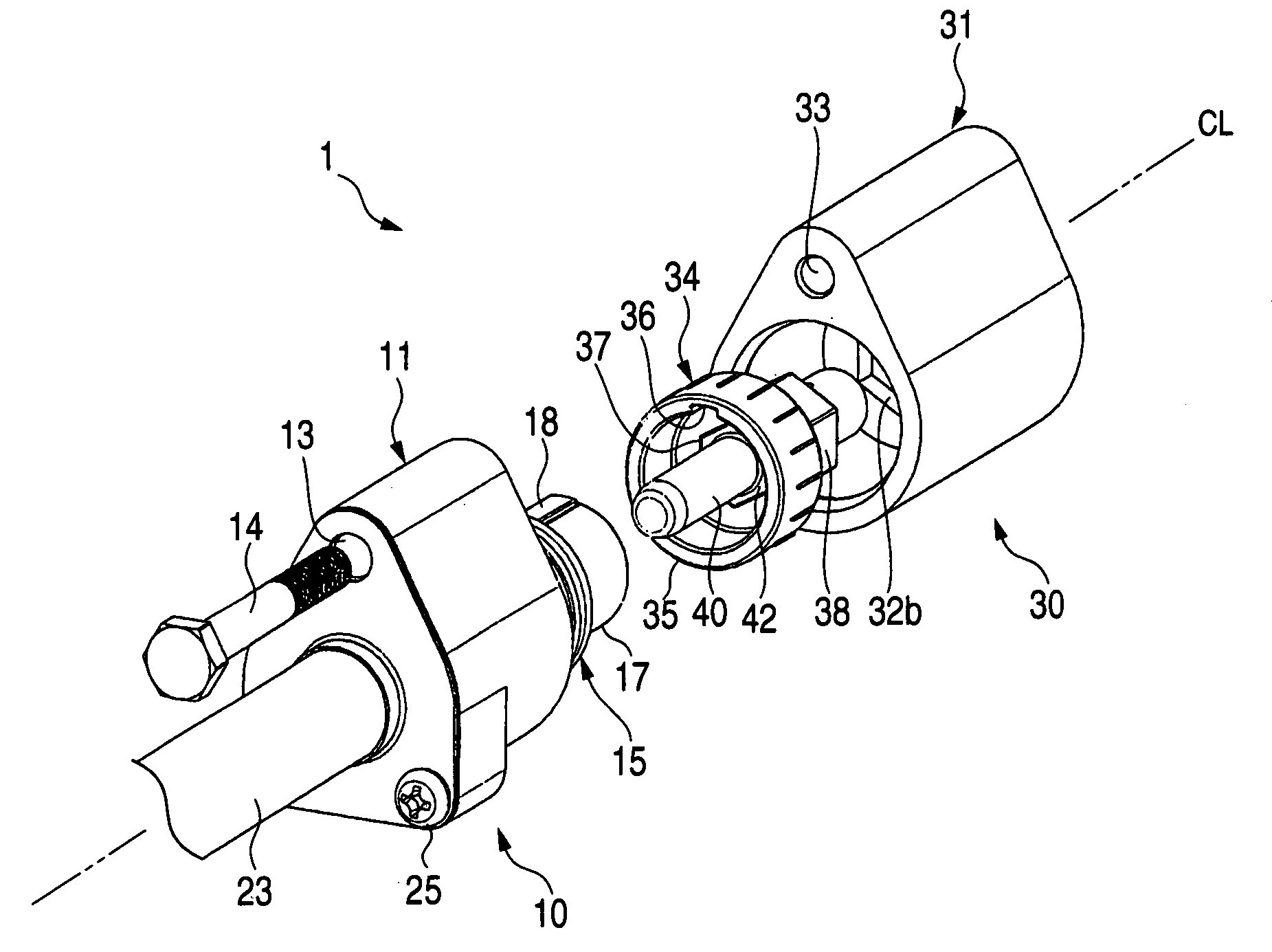
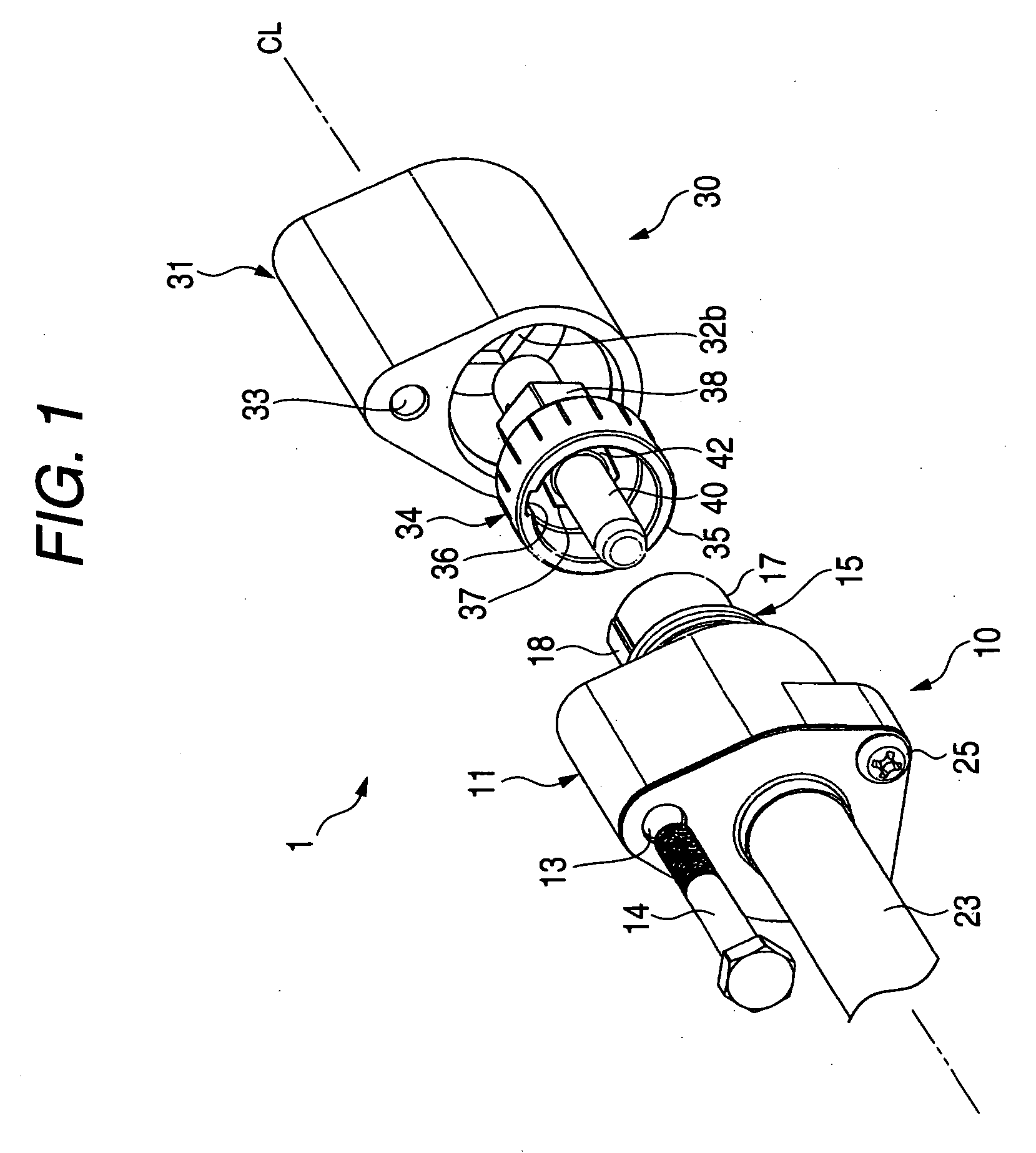
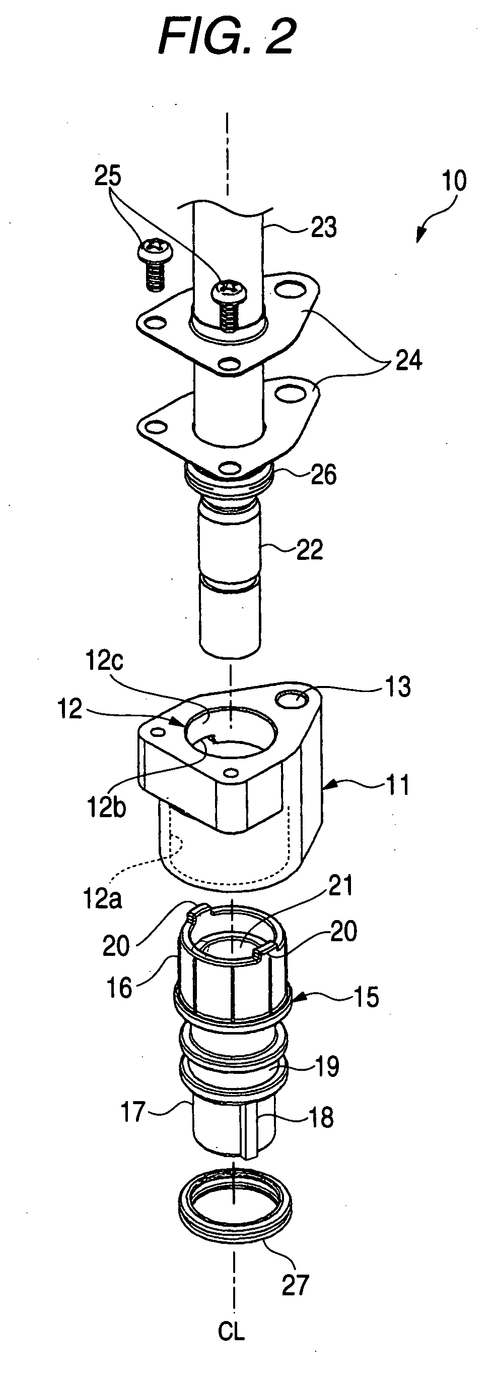
[0058]FIG. 1 is a perspective view of a first embodiment of a female-male connector-fitting structure of the invention, showing its appearance, FIG. 2 is an exploded, perspective view of a male connector shown in FIG. 1, FIG. 3A is an exploded, perspective view of a female connector shown in FIG. 1, FIG. 3B is a partly-broken perspective view of a female adapter shown in FIG. 3A, and FIGS. 4A to 4C are perspective explanatory views of the manner of attaching the female adapter when forming a plurality of pairs of female and male connectors.

[0059] As shown in FIGS. 1 to 3B, the female-male connector-fitting structure 1 is a structure for fitting the female connector 30 and the male connector 10 together, and this fitting structure 1 is used for connecting a wire (or cable) 23 such as a shielded wire to an electrical equipment or a wire. An axis CL, shown in FIGS. 1 to 3B, is an axis serving as a reference when fitting the male and female connectors 10 and 30 together.

[0060] First, ...

second embodiment

[0090] Next, a second embodiment of a female-male connector-fitting structure of the invention will be described with reference to FIGS. 5 to 6C. FIG. 5 is an exploded, perspective view of a male connector of the female-male connector-fitting structure of the second embodiment, and FIGS. 6A to 6C are perspective explanatory views of the manner of attaching the male adapter and the female adapter when forming a plurality of pairs of female and male connectors. In the female-male connector-fitting structure 2 of this embodiment, the male inner housing 15 of the male connector 10 of the female-male connector-fitting structure 1 of the above first embodiment is so modified that it can be rotated relative to the male housing 11 to be placed at the selected one of a plurality predetermined angular positions arranged with the fixed interval, and is attached to the male housing 11. The other members are identical to those of the first embodiment, respectively, and therefore will be designat...


PUM


Abstract

In a structure of fitting female and male connectors together, the female connector includes a female housing, and a female adapter which is provided on the female housing, and has a guide groove, and is fitted on a fitting portion provided at the male connector. The male connector includes a guide rib which is formed at the fitting portion, and is engageable in the guide groove. The female adapter can be rotated relative to the female housing to be placed at any of a plurality predetermined angular positions arranged with a fixed interval, and can be attached to the female housing. Only when the female adapter is rotated into a preselected one of the plurality predetermined angular positions, and is attached to the female housing of the female connector, the guide rib can be fitted in the guide groove, thereby allowing the female and male connectors to be fitted together.

Description

BACKGROUND OF THE INVENTION [0001] This invention relates to a structure of fitting female and male connectors together. [0002] Female and male connectors have been used for electrically connecting a wire (or cable) to an electrical equipment or a wire, and in order to prevent the erroneous fitting of the two connectors, there has been used the type of female and male connectors, in which a guide groove is formed in a connector housing of the female connector, and a guide rib for engagement in the guide groove is formed on a connector housing of the male connector (see, for example, JP-A-2002-117947). [0003] As shown in FIGS. 7A, 7B and 8, the male connector 102 and female connector 103, disclosed in Patent Literature 1, are shield connectors which are used for connecting a shielded wire (or cable) 109 to an electrical equipment or the like, and are mounted on an automobile. [0004] The male connector 102 includes an inner housing 121 made of an insulative synthetic resin, and an out...

Claims


Application Information

Patent Timeline
Patent Type & Authority Applications(United States)
IPC IPC(8): H01R13/64H01R24/58
CPCH01R13/64H01R2103/00H01R24/542
Inventor ISHIZAKI, KAZUHISAAOKI, EIJI
Owner YAZAKI CORP
Why Eureka
Try Eureka