Heat exchanger fins and method for fabricating fins particularly suitable for stirling engines

a technology of heat exchangers and fins, which is applied in the field of heat exchangers, can solve the problems of not being able to achieve the optimal transfer of heat from a surrounding gas burner into the head, and achieve the effect of facilitating bending into the helix

Inactive Publication Date: 2006-02-09
SUNPOWER
View PDF25 Cites 9 Cited by
  • Summary
  • Abstract
  • Description
  • Claims
  • Application Information

AI Technical Summary

Problems solved by technology

Fins which are formed of parallel planar surfaces are desirable for optimizing the transfer of heat from an engine head to a surrounding fluid but are not optimal for transferring heat from a surrounding gas burner into the head.

Method used


Image

  • Heat exchanger fins and method for fabricating fins particularly suitable for stirling engines
  • Heat exchanger fins and method for fabricating fins particularly suitable for stirling engines
  • Heat exchanger fins and method for fabricating fins particularly suitable for stirling engines

Examples


Embodiment Construction

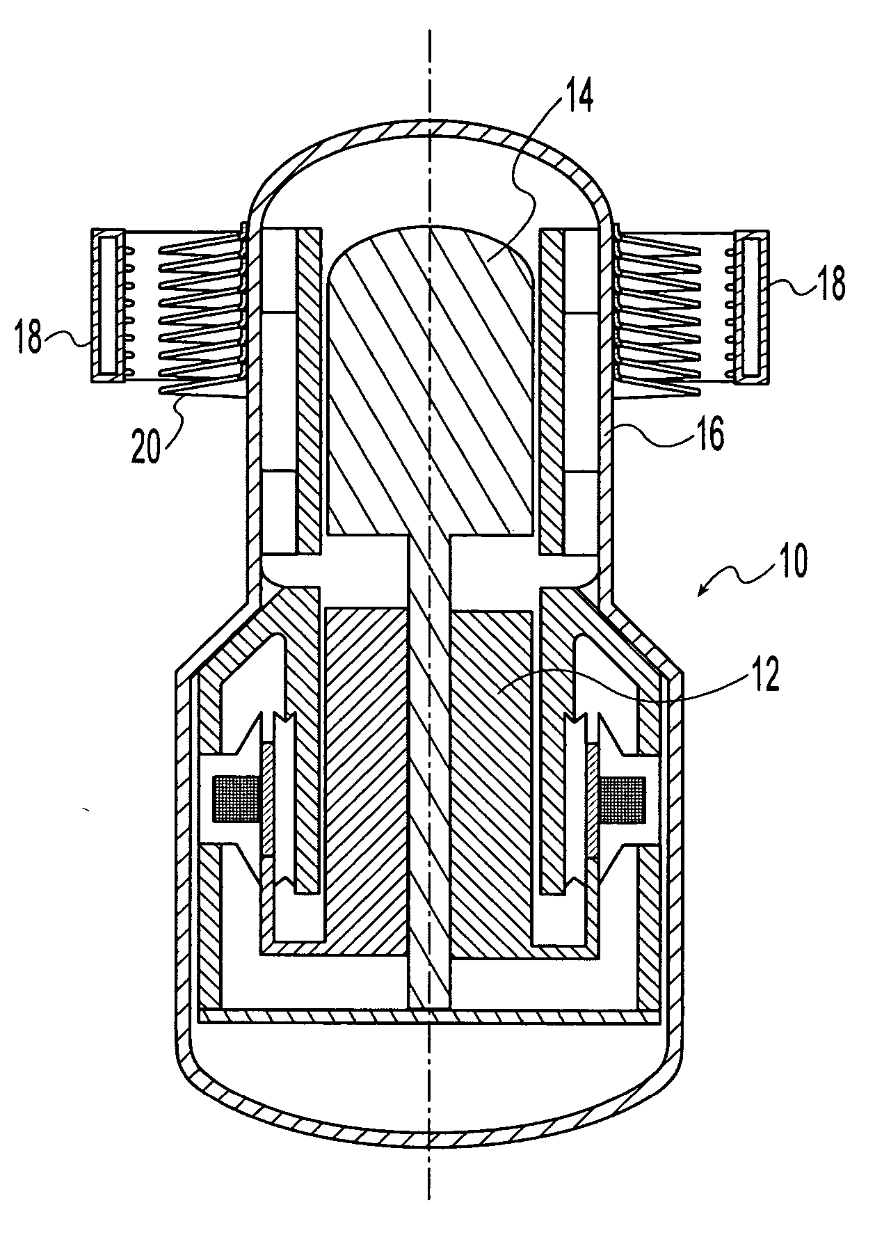
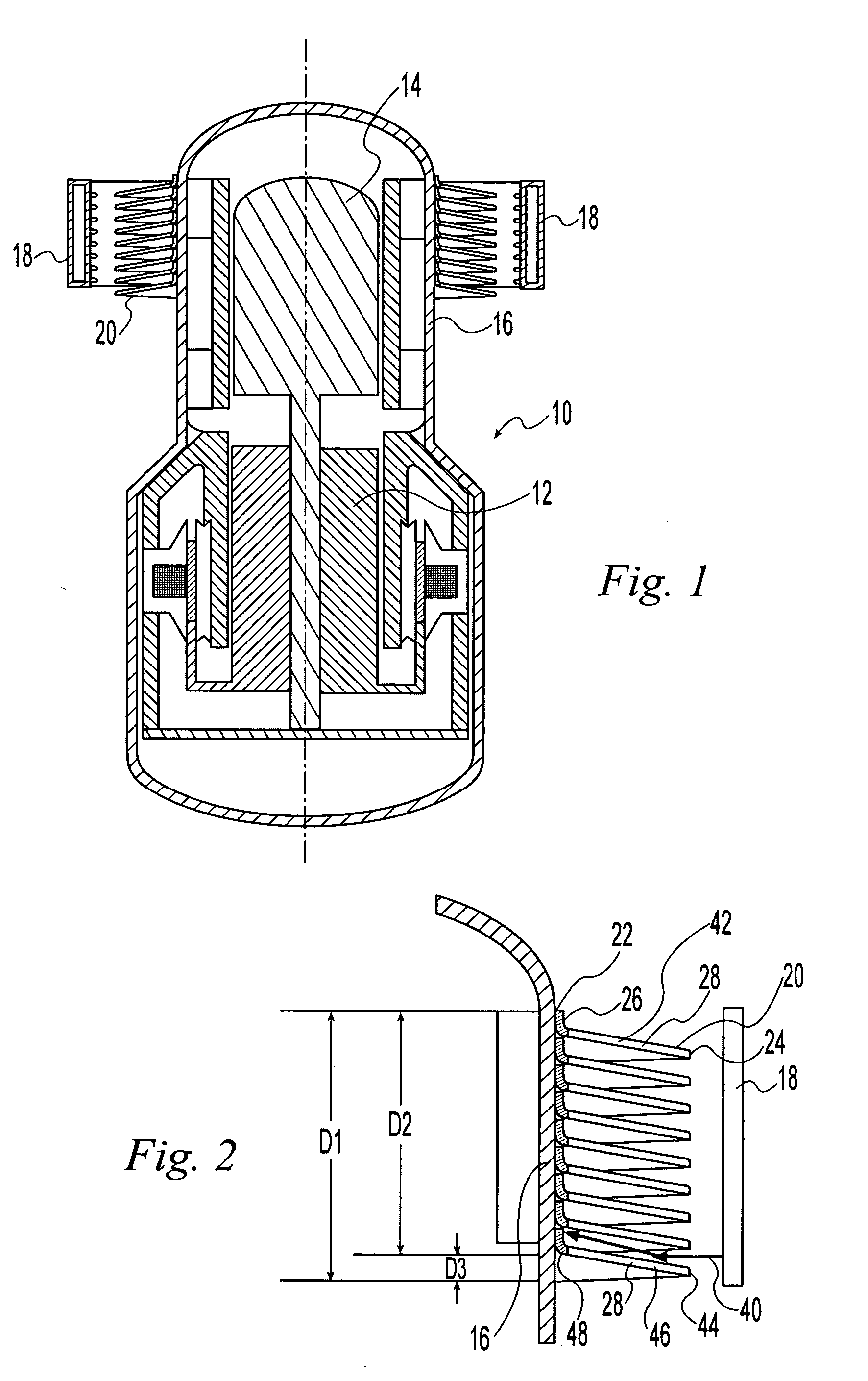
[0020]FIG. 1 illustrates a free piston Stirling engine 10 having a conventional power piston 12 and a displacer 14, which reciprocates in an engine head 16. The engine is powered by heat applied from a ring burner 18 surrounding the head 16. The heat is supplied by burner flames fueled by gas supplied into an interior chamber of the burner 18 from a fuel source and expelled through a matrix of orifices to each flame. The transfer of heat into the Stirling engine head 16 causes the alternate expansion and contraction of a working gas within the Stirling engine in accordance with well established principles of Stirling engine operation.

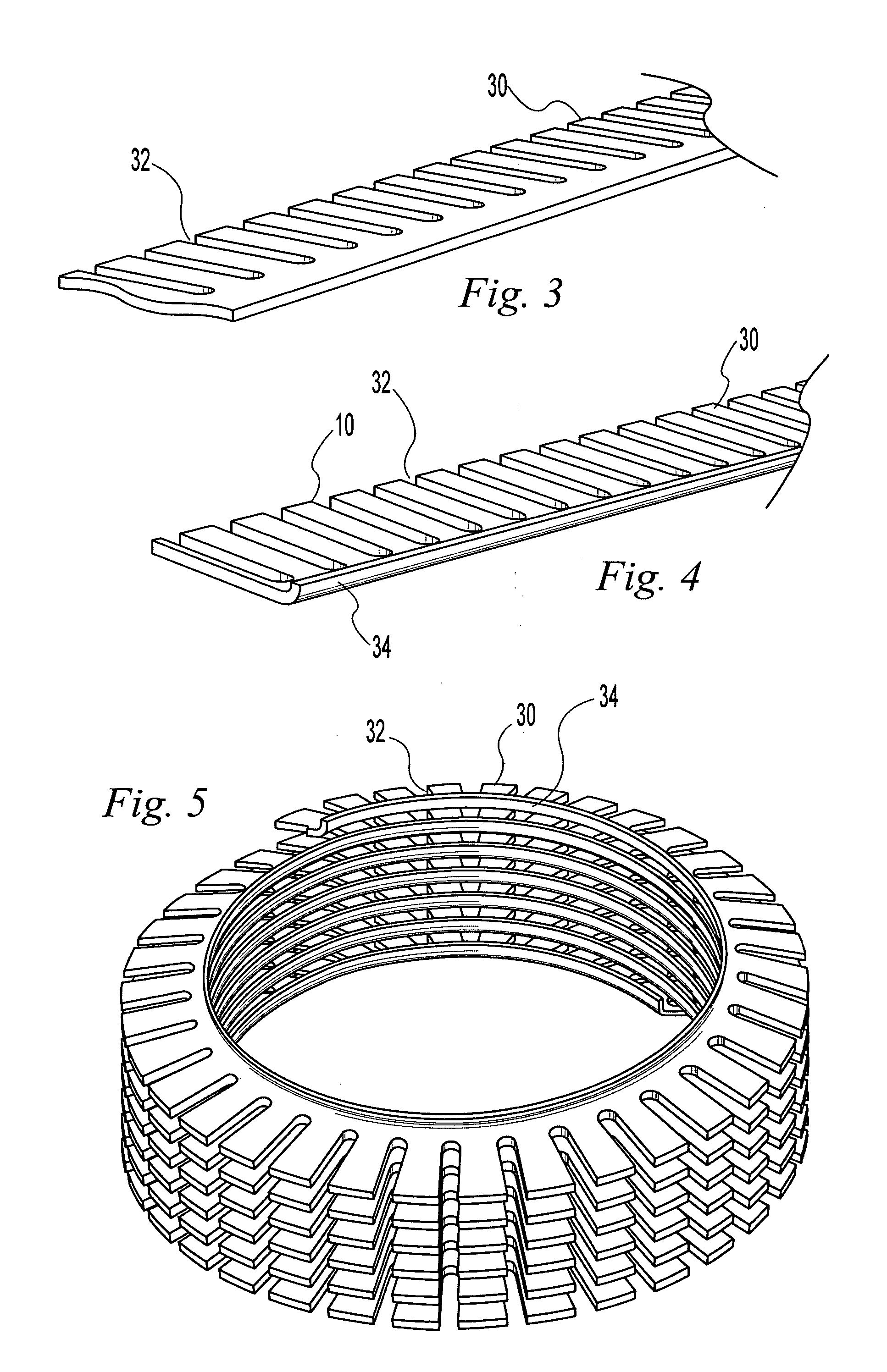
[0021] In order to improve the rate and efficiency of heat transfer into the head, it is known in the prior art to provide a heat exchanger on the exterior of the head 16. Thermally conductive, axially spaced fins surrounding and attached to the head of a Stirling engine have been used for such heat exchangers. Such fins are usually planar and extend r...


PUM

PropertyMeasurementUnit
thermally conductiveaaaaaaaaaa
diameteraaaaaaaaaa
massaaaaaaaaaa

Abstract

Heat exchanger fins and a method for fabricating fins particularly suitable for the head of Stirling engine. The fins have a frusto-conical contour and surround and are brazed to the heater head at axially spaced positions. The inner edges of the fins are rolled to provide a flange for engaging and being joined to the head and have axially aligned, radial slots cut into the outer edge to provide channels for the passage of the products of heater combustion. The fins can be formed of annular rings or from a ribbon bent into a helix.

Description

BACKGROUND OF THE INVENTION [0001] 1. Field of the Invention [0002] This invention relates generally to heat exchangers and more specifically, to simple fin structures for heat exchangers and a method for manufacturing fins for facilitating heat transfer. [0003] 2. Description of the Related Art [0004] Heat exchangers are commonly used in a variety of machines to improve the heat transfer rate from a mass at a higher temperature to a mass at a cooler temperature. [0005] Axially spaced fins are a well know heat exchanger structure and are commonly used for cooling a component of a machine, such as the cylinder of a small, air cooled, internal combustion engine, by transferring heat from the machine component to the surrounding atmosphere. Fins have also been used to assist in the transfer of heat from a heat source, such as a gas burner, into an external combustion machine, such as a free piston Stirling engine. Fins are effective because they provide highly thermally conductive path...

Claims


Application Information

Patent Timeline
Patent Type & Authority Applications(United States)
IPC IPC(8): B23P15/26
CPCB21D11/06B23P15/26Y10T29/49382F02G2255/20F28F1/36F02G1/055
Inventor WOOD, JAMES GARY
Owner SUNPOWER
Why Eureka
Try Eureka