Vegetation trimmer apparatus

a technology of vegetable trimming and trimmer, which is applied in the field of vegetable trimming apparatus, can solve the problems of increasing affecting the service life of the blade, and affecting the service life of the trimmer, so as to reduce the likelihood of seizure or failure, reduce the waste of the trimmer line, and facilitate the loading and unloading

Inactive Publication Date: 2006-02-09
SPECIALTY COATED PROD +1
View PDF28 Cites 29 Cited by
  • Summary
  • Abstract
  • Description
  • Claims
  • Application Information

AI Technical Summary

Benefits of technology

[0012] The present invention relates to vegetation trimmer apparatus having trimmer heads comprising mechanical trimmer line clamping mechanisms that are reliable and easy to load and unload. The clamping means include clamping members that are biased into a trimmer line gripping position by springs or similar biasing means. The gripping members are operably connected to release means for assisting in the discharge of worn trimmer line from the trimmer head. The clamping means are disposed in a chamber that is effectively closed to the lower surface of the trimmer head housing such that dirt and debris cannot enter the chamber and clog the clamping means. In addition to a reduced likelihood of seizure or failure of the clapming means, the enclosed chamber affords other advantages which are not collectively achievable by presently available vegetation trimmer heads having mechanical trimmer line clamping mechanisms. Namely, the chambers enable relatively short lengths of trimmer line to be used, thereby reducing waste of trimmer line, and enable trimmer line of any cross-sectional configuration to be used in the trimmer head.

Problems solved by technology

If rigid, the cutting means assume the form of blades fabricated from plastic and / or metal and often have corrugations about their peripheral cutting edges.
The blades are pivotally attached to the trimmer head such they yield when they contact hard objects, thereby prolonging the service lives of the blades.
Rigid blades are normally used to cut very dense vegetation and may cause considerable injury to the trimmer operator or other persons should they accidentally be struck by the blades during operation of the trimmer.
A disadvantage of these sorts of devices is that the line frequently becomes jammed when a user attempts to dispense fresh line from the spool.
The jam may be the result of partial fusion of the coils of line or the line becoming entangled.
Such repeated disruption can be quite frustrating and time-consuming.
It is particularly exasperating for professionals in the business of mowing and grooming lawns because of the significant amount of lost time involved.
Each of these designs suffers from one or more of the following disadvantages: (1) trimmer line with enlarged, knotted or otherwise modified ends must be used to retain the strings in the trimmer head, resulting in additional manufacturing cost and / or installation difficulty, (2) trimmer line of undue length is required for operation, thereby resulting in wasted trimmer line, and (3) trimmer line heads using mechanical trimmer line clamping mechanisms can become clogged with dirt and debris, thereby resulting in failure or seizure of the clamping mechanism.
In addition, trimmer line heads using mechanical trimmer line clamping mechanisms are easy to load but can sometimes be difficult to unload.
Frequently, a user may experience difficulty in removing the trimmer line because a clamping member grips the trimmer line so tightly that it becomes fixedly embedded in the trimmer line.
In that instance, the trimmer line cannot be removed by many persons by merely grasping the line and pulling it out of the device.
Consequently, dirt and debris churned up through operation of the trimmer head can enter the holes, clog the clamping mechanisms and render them stiff or even unusable, notwithstanding the presence of the release buttons.

Method used


Image

  • Vegetation trimmer apparatus
  • Vegetation trimmer apparatus
  • Vegetation trimmer apparatus

Examples


Embodiment Construction

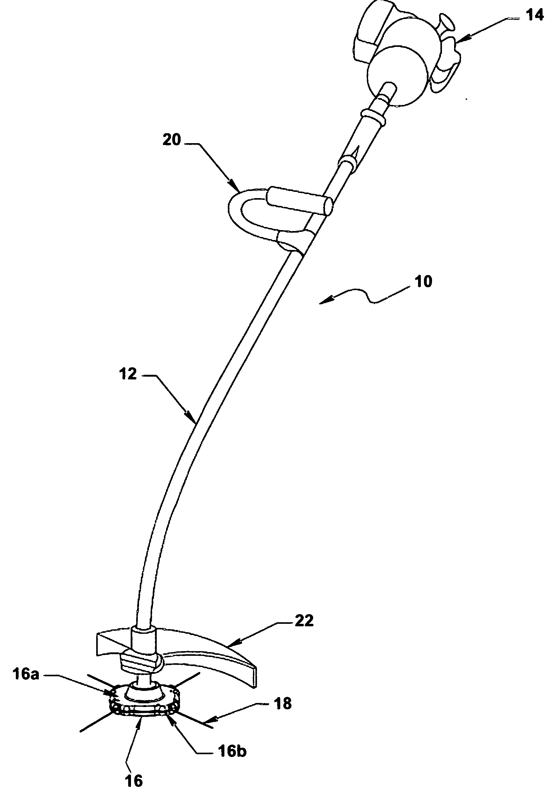
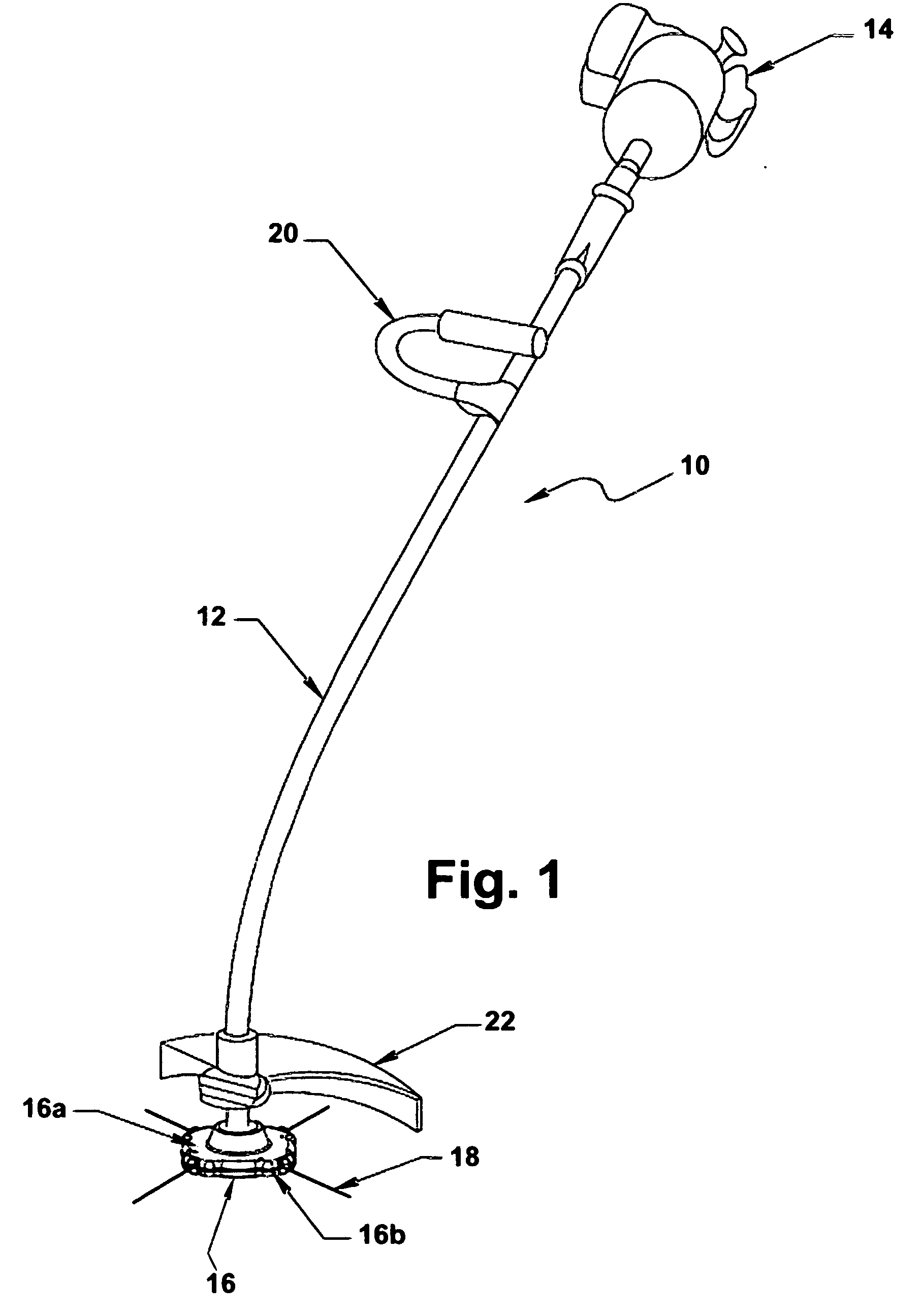
[0024] Referring to the drawings wherein like or similar references indicate like or similar elements throughout the several views, there is shown in FIG. 1 a typical motorized vegetation trimmer apparatus 10. Apparatus 10 comprises an elongate main handle 12 which to which is connected an internal combustion or electric motor 14 that rotatably drives a trimmer head 16 located at a distal end of the handle. Trimmer head 16 carries one or more radially outwardly projecting cutting means 18 which cut the vegetation as the trimmer head rotates. Preferably, trimmer apparatus 10 includes a steering handle 20 attached to the main handle 12 to facilitate guidance of the apparatus during operation. A shield 22 is also desirably provided for the operator's safety.

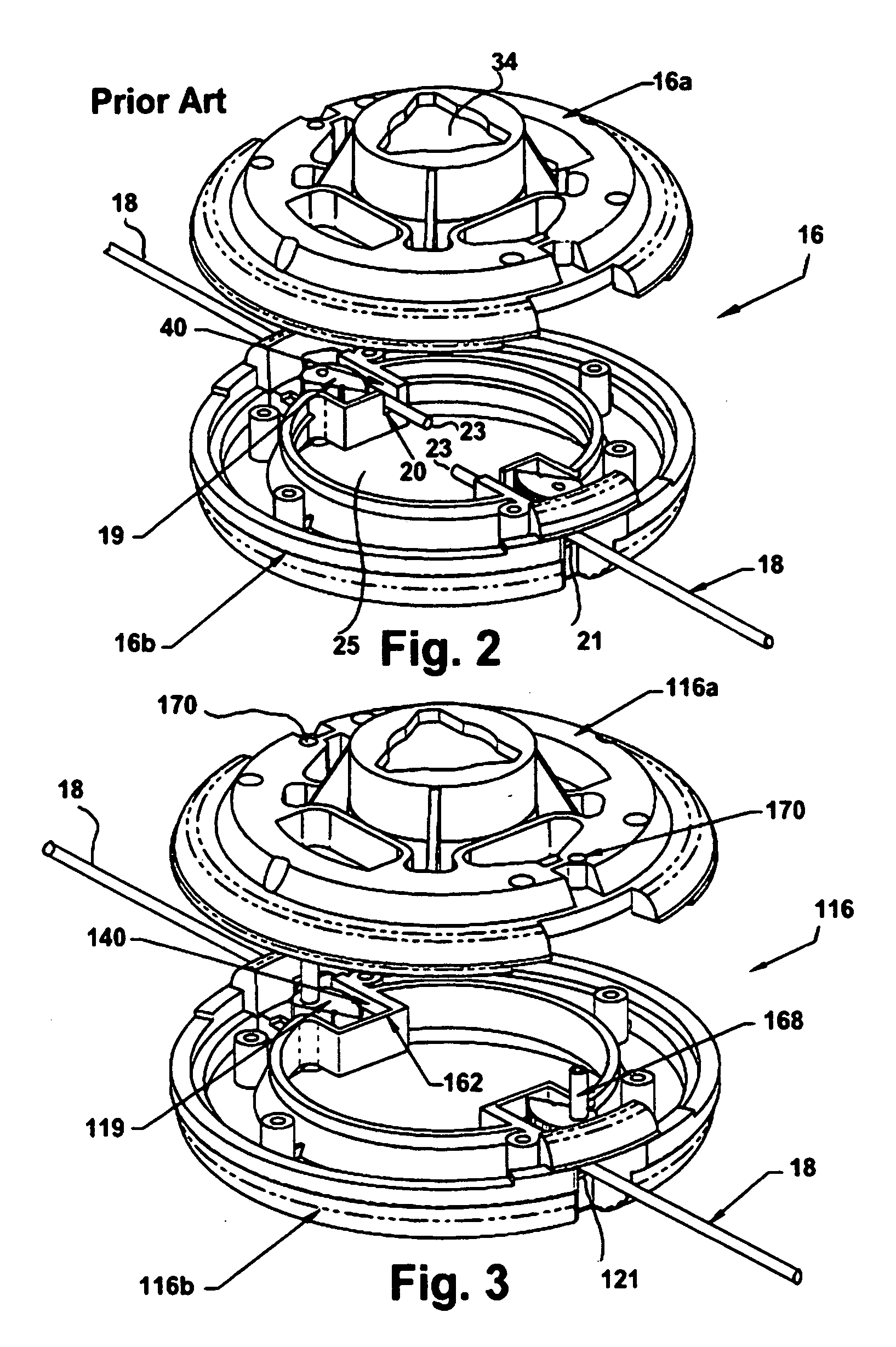
[0025] Referring to FIG. 2 there is shown a conventional fixed line trimmer head 16 that is used for cutting vegetation in conjunction with an internal combustion or electric powered trimmer apparatus such as apparatus 10 shown in ...


PUM


Abstract

A motorized vegetation trimmer apparatus comprising an elongate main handle to which is connected a motor that rotatably drives a trimmer head located at a distal end of the handle. The trimmer head carries one or more radially outwardly projecting cutting members which cut vegetation as the trimmer head rotates. Each cutting member comprises a finite length of flexible strand. The cutting member is releasably gripped in a substantially enclosed chamber by a gripping mechanism including a movable gripping member and a spring that biases the gripping member into gripping contact with the strand. A release member cooperates with the gripping member to urge the gripping member against the biasing force of the spring to permit removal of a cutting member from the trimmer head.

Description

CROSS REFERENCE TO RELATED APPLICATION [0001] The present application claims the benefit of U.S. Provisional Patent Application No. 60 / 598,054 filed Aug. 3, 2004, which is incorporated herein by reference in its entirety.FIELD OF THE INVENTION [0002] The present invention relates in general to vegetation trimmer apparatus and in particular to vegetation trimmer apparatus having flexible cutting members of finite length. BACKGROUND OF THE INVENTION [0003] Internal combustion engine and electric motor powered vegetation trimmers are commonly used to cut and trim grass, weeds, brush and other vegetation. The typical motorized trimmer comprises an elongate handle to which is connected an internal combustion or electric motor that rotatably drives a trimmer head located at a distal end of the handle. The trimmer head, in turn, carries one or more radially outwardly projecting cutting members which cut the vegetation as the trimmer head rotates. [0004] The cutting members may include one ...

Claims


Application Information

Patent Timeline
Patent Type & Authority Applications(United States)
IPC IPC(8): B26B7/00
CPCA01D34/416
Inventor ALLISS, GEORGE E.
Owner SPECIALTY COATED PROD
Why Eureka
Try Eureka