Tool apparatus

Inactive Publication Date: 2006-02-09
T WORX HLDG LLC
View PDF20 Cites 1 Cited by
  • Summary
  • Abstract
  • Description
  • Claims
  • Application Information

AI Technical Summary

Benefits of technology

[0004] The distance between the tip of the cutting insert and an outboard face of the set screw diameter of the tool holder defines what is known as the unsupported overhang of the boring bar. In general, the greater the ratio between the length of the unsupported overhang to the diameter of the boring bar—the lesser the rigidity of the tool setup. Lesser tool rigidity results in tool vibration and chatter, thereby necessitating reductions in machining federates and throughput in order to maintain workpiece accuracy and surface finish.
[0005] Boring of workpieces having stepped diameters, or variably sized internal features, presents a special probl

Problems solved by technology

Boring of workpieces having stepped diameters, or variably sized internal features, presents a special problem for boring tools.
Such an interruption is a major risk to workpiece accuracy for at least a couple of reasons.
First, using a smaller diameter boring bar sacrifices tool rigidity due to a corresponding decrease in cross-sectional surface area and beam strength of the tool.
Second, a tool change disrupts the dimensional relationship between the shallower, large diameter and the deeper, smaller diameter since two different tools must be used.
Simply put, using two different tools is undesirable since the subsequent tool will not necessarily pick up exactly where the original tool left off in the cut.
Moreover, using two different tools results in increased manufacturing time and costs.
First, interrupting the machining operation to execute a tool change results in increased machine cycle time.
Thus, where time is money, unnecessarily slow machining performance translates into unnecessarily high manufacturing costs.
Another special problem with boring involves the interconnection of carbide boring bars to boring bar tool holders.
The longitudinal flats present two problems.
First, incorporating longitudinal flats along a boring bar yields less tool rigidity.
Second, setscrews do not always squarely engage the longitudinal flats of the boring bar despite being tightly fastened down.
Third, setscrews only engage a small area of the boring bar roughly equal to the diameter of the point of the setscrew.
The above problems manifest themselves in the form of unnecessarily compromised rigidity of the boring bar tool setup, and an attendant decrease in workpiece quality and / or increase in machining time and cost.

Method used


Image

  • Tool apparatus
  • Tool apparatus
  • Tool apparatus

Examples


Embodiment Construction

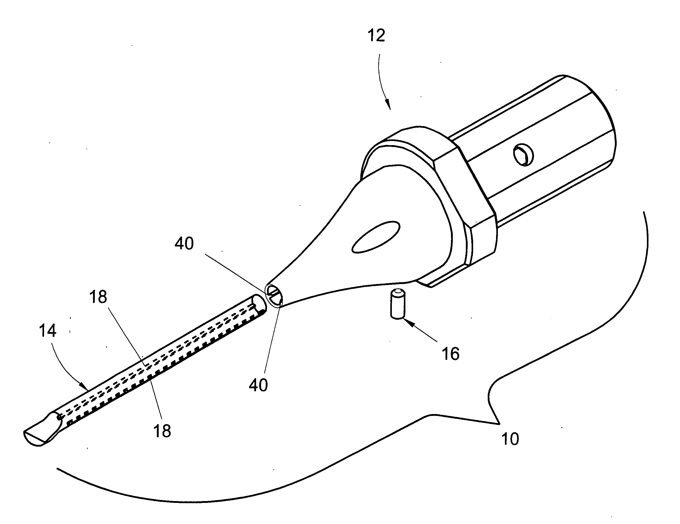
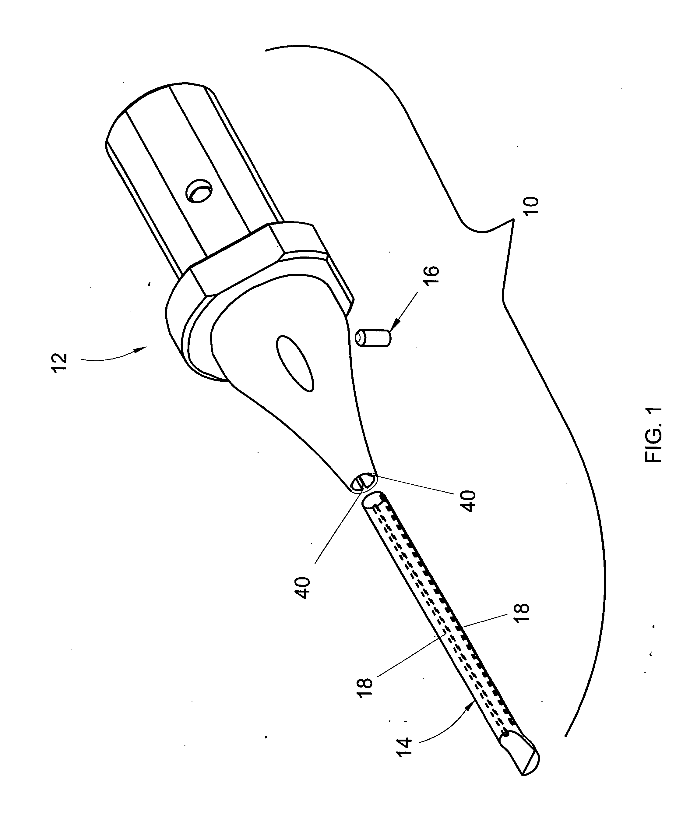
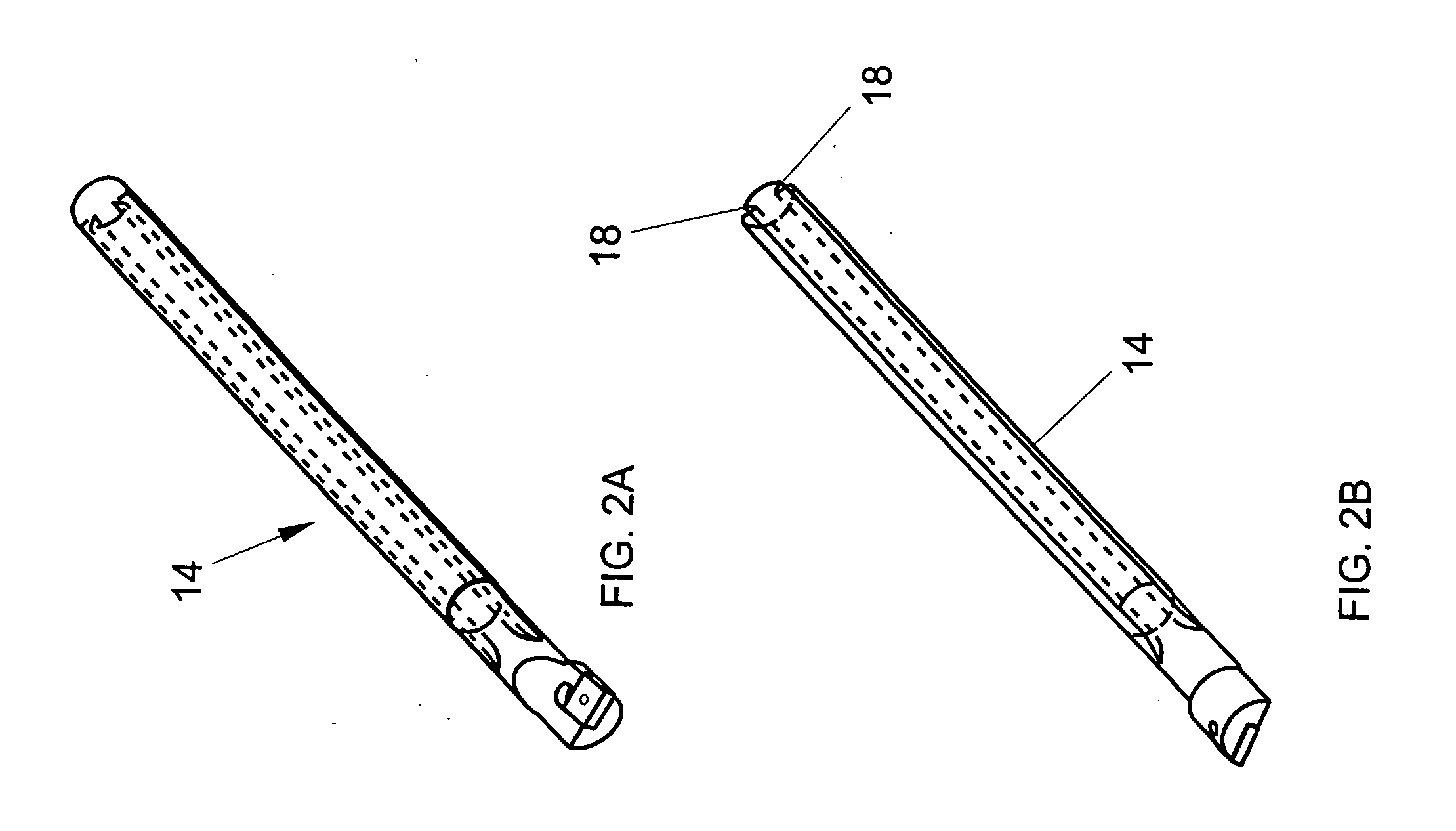
[0030] The present invention is not limited in its application to the details of any particular arrangement described or shown, since the present invention is capable of multitudes of embodiments without departing from the spirit and scope of the present invention. First, the principles of the present invention are described by referring to only a few exemplary embodiments for simplicity and illustrative purposes. Although only a limited number of embodiments of the invention are particularly disclosed herein, one of ordinary skill in the art would readily recognize that the same principles are equally applicable to, and can be implemented in types of tooling. Furthermore, numerous specific details are set forth below and in the drawing figures to convey with reasonable clarity the inventor's possession of the present invention, descriptions of how to make and / or use the present invention, and the best mode in carrying out the present invention known to the inventor's at the time of...


PUM


Abstract

A cutting tool apparatus having a shank and a tool support extension disposed longitudinally adjacent the shank and extending in a direction distal the shank, wherein the tool support extension includes an incurvate taper profile.

Description

BACKGROUND AND SUMMARY OF THE INVENTION [0001] Tool holders are used in various machine tools, such as turning centers and lathes, for the purpose of holding a variety of different tools such as boring bars. Boring bars are typically used by a turning center machine tool during a boring operation, the purpose of which is to increase the size of pre-existing internal features of a workpiece while obtaining target size and surface finish accuracy. Under very rigid tool setups, boring operations are often capable of maintaining a size tolerance within 0.0002″. [0002] A turning center machine tool includes a workpiece spindle for holding and spinning a workpiece, and may further include a tool spindle, tail-stock, or tool turret for holding a tool holder and tool. A tailstock typically includes a socket into which a rearward end of the tool holder is inserted. Some tool holders have a generally cylindrical shank that extends forward from the rearward end and that includes one or more lo...

Claims


Application Information

Patent Timeline
IPC IPC(8): B25G3/00B23B29/04
CPCB23B29/04Y10T82/2585Y10T407/2272Y10T408/95Y10T407/227
Inventor TRAVEZ, ITALO D.TRAVEZ, JOSE M.CABAHUG, ERIC F.
Owner T WORX HLDG LLC
Why Eureka
Try Eureka