Methods and apparatus for regulating airflow supply systems

Active Publication Date: 2006-02-09
UNISON INDUSTRIES
View PDF11 Cites 13 Cited by
  • Summary
  • Abstract
  • Description
  • Claims
  • Application Information

AI Technical Summary

Benefits of technology

[0006] In another aspect, a check valve is provided that includes a valve housing that has a side wall and a flow path therethrough, the side wall defining the flow path. The flow path includes an inlet, an outlet, and a centerline extending between the inlet and the outlet. At least one control member is positioned in the flow path and movable between a first position, wherein fluid flow through the valve housing is substantially prohibited and a second position wherein fluid flow is permitted. The side wall includes a stop configured to limit movement of the at least one control member at a pre-determined stop angle relative to the flow path centerline.
[0007] In a further aspect, a gas turbine engine bleed air supply system is provided. The bleed air supply system includes a bleed duct having first and second ends. The first end is coupled to

Problems solved by technology

Because the pressure of air bled from a specific bleed port may change significantly as engine operating conditions change, it may not be possible, without undue complexity and costs, to provide exactly the correct pressure to the ECS from the same bleed port.
During engine operation, the check valves may be subjected to vibrational stresses induced by the engine and

Method used


Image

  • Methods and apparatus for regulating airflow supply systems
  • Methods and apparatus for regulating airflow supply systems
  • Methods and apparatus for regulating airflow supply systems

Examples


Example

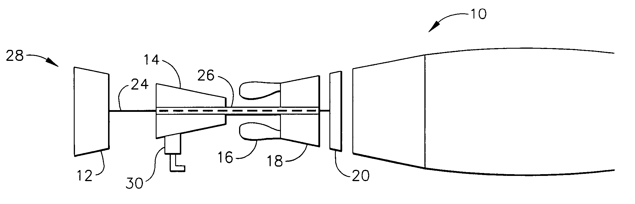
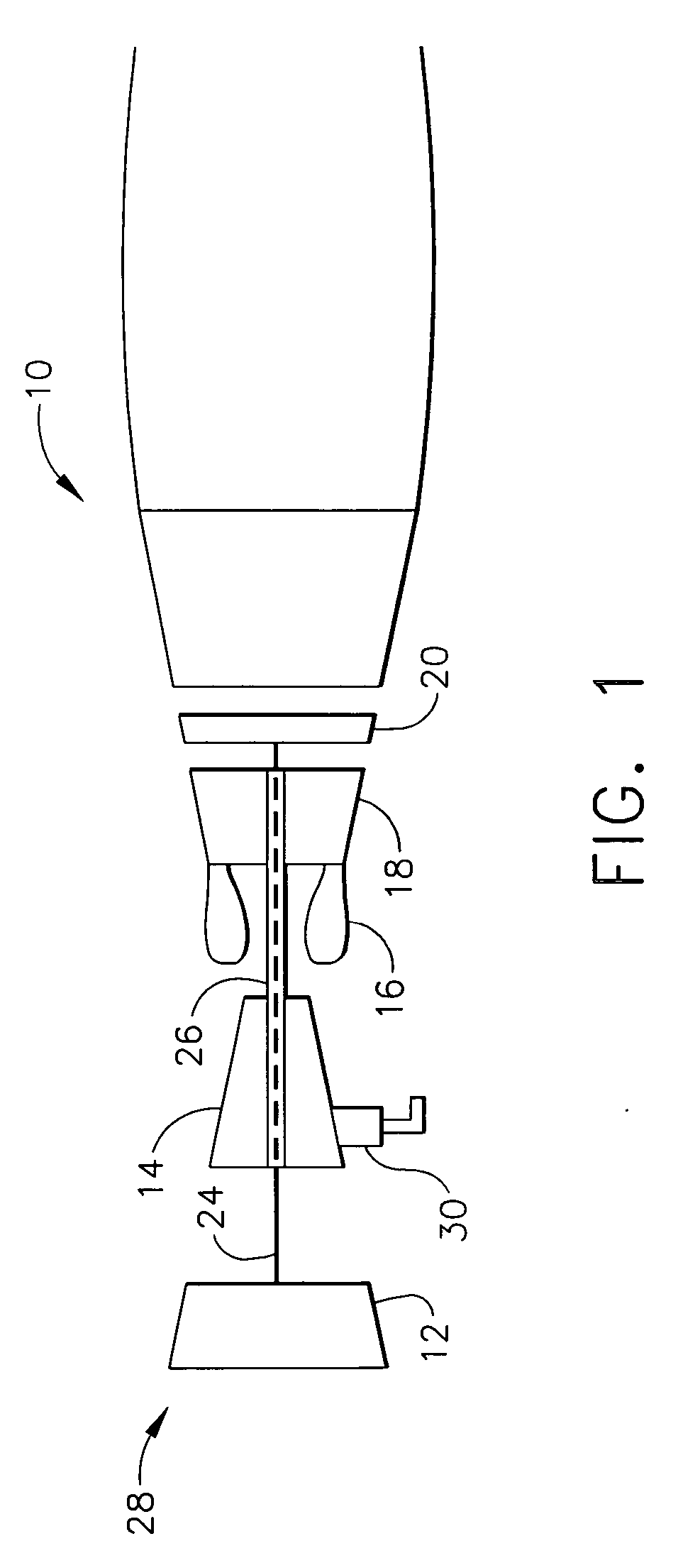
[0014]FIG. 1 is a schematic illustration of an exemplary gas turbine engine 10. Engine 10 includes a low pressure compressor 12, a high pressure compressor 14, and a combustor assembly 16. Engine 10 also includes a high pressure turbine 18, and a low pressure turbine 20 arranged in a serial, axial flow relationship. Compressor 12 and turbine 20 are coupled by a first shaft 24, and compressor 14 and turbine 18 are coupled by a second shaft 26. In one embodiment, engine 10 is a GP7200 engine commercially available from General Electric Aircraft Engines, Cincinnati, Ohio. Engine 10 includes a bleed air supply system 30 coupled to compressor 14. In an exemplary embodiment, air is bled from a fourth stage of compressor 14.

[0015] In operation, air flows through low pressure compressor 12 from an upstream side 28 of engine 10. Compressed air is supplied from low pressure compressor 12 to high pressure compressor 14. Bleed air supply system 30 extracts bleed air from compressor 14 for use ...


PUM


Abstract

A check valve is provided that includes a valve housing that has a side wall and a flow path therethrough, the side wall defining the flow path. The flow path includes an inlet, an outlet, and a centerline extending between the inlet and the outlet. At least one control member is positioned in the flow path and movable between a first position, wherein fluid flow through the valve housing is substantially prohibited and a second position wherein fluid flow is permitted. The side wall includes a stop configured to limit movement of the at least one control member at a pre-determined stop angle relative to the flow path centerline.

Description

BACKGROUND OF THE INVENTION [0001] This invention relates generally to gas turbine engines and more particularly, to engine bleed air systems used with gas turbine engines. [0002] Gas turbine engines used in aircraft propulsion systems typically include a bleed air system that routes air from a compressor section of the engine to an environmental control system (ECS) on the aircraft. For example, in at least some engines, bleed air is bled from the compressor through holes or ports formed in the compressor housing. However, bleed air routed from the compressor section is generally at a higher pressure and temperature than desired for use by the ECS, and is therefore conditioned prior to use. More specifically, at least some known ECS include various components, such as regulating valves and heat exchangers, to condition the bleed air for use by the ECS. [0003] Because the pressure of air bled from a specific bleed port may change significantly as engine operating conditions change, ...

Claims


Application Information

Patent Timeline
IPC IPC(8): F02C6/08F16K15/03
CPCF16K15/038F02C6/08Y10T137/7839Y10T137/7898F16K15/03
Inventor CHRISTIANSON, ERIC JONMYERS, JERRY WAYNEHAND, JOHN MATHEWBOWERS, KEVIN TODD
Owner UNISON INDUSTRIES
Why Eureka
Try Eureka