Rapid response solenoid for electromagnetic operated valve

a technology of electromagnetic operation and solenoid, which is applied in the direction of valve operating means/release devices, magnets, magnetic bodies, etc., can solve the problems of power consumption, preclude the desired solenoid wattage and/or valve operating speed, etc., to reduce friction and magnetic attraction of the armature, increase the de-energized return speed of the valve, and increase the operating wattage

Inactive Publication Date: 2006-02-09
MAC VALVES INC
View PDF25 Cites 21 Cited by
  • Summary
  • Abstract
  • Description
  • Claims
  • Application Information

AI Technical Summary

Benefits of technology

[0007] According to another preferred embodiment of the present invention, the stationary pole plate is positioned at a bobbin first end having a portion of the pole plate extending within a through aperture formed in the bobbin. A bushing is disposed within the through aperture and substantially fixed in relation to the bobbin. The bushing is positioned between the armature and an inner wall of the bobbin and provides a sliding fit between the armature and the bobbin inner wall. A brass or other non-magnetic material used for bushing reduces friction and magnetic attraction of the armature to the bushing and therefore increases a de-energized return speed of a valve connected to the solenoid.
[0008] Advantages of the present invention include the capability of accepting higher operating wattages, a faster cycle time for an attached valve and a solenoid assembly less susceptible to wear from friction of the moving parts. A smaller wire size is also used which provides additional benefit to the solenoid operating force and power generated. By using the geometry for a solenoid of the present invention, an improved cycle time at a given solenoid size is also provided.

Problems solved by technology

The patent to Sato et al. also identifies a known method to calculate the attraction force generated between an armature and a pole plate, and a power consumption.
The limited ratio range of Sato restricts the geometry of the solenoid and therefore can preclude a desired solenoid wattage and / or valve operating speed for narrow or tightly arranged solenoid / valve applications.

Method used


Image

  • Rapid response solenoid for electromagnetic operated valve
  • Rapid response solenoid for electromagnetic operated valve
  • Rapid response solenoid for electromagnetic operated valve

Examples


Embodiment Construction

[0015] The following description of the preferred embodiments is merely exemplary in nature and is in no way intended to limit the invention, its application, or uses.

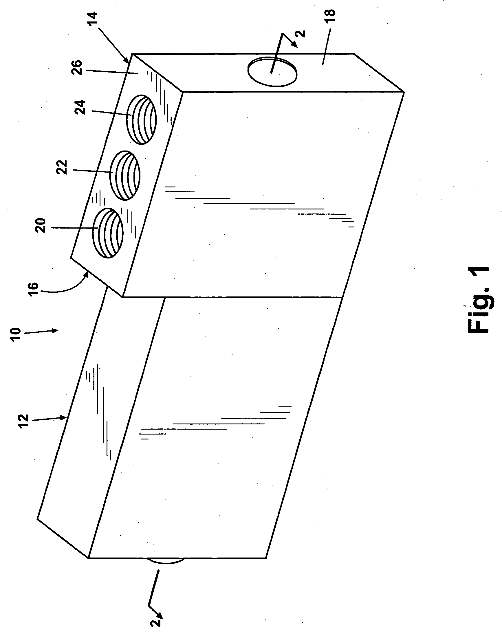
[0016] According to a preferred embodiment of the present invention and referring generally to FIG. 1, a valve assembly 10 includes a solenoid 12 connectably attached to a valve body 14 at a valve body mounting face 16. Internal components of valve body 14 are generally loaded via a valve loading face 18. A valve body inlet port 20, and outlet port 22 and an exhaust port 24 are exemplary of fluid ports disposed via a fluid system service face 26 of valve body 14. The invention is not limited to a particular orientation or quantity of ports.

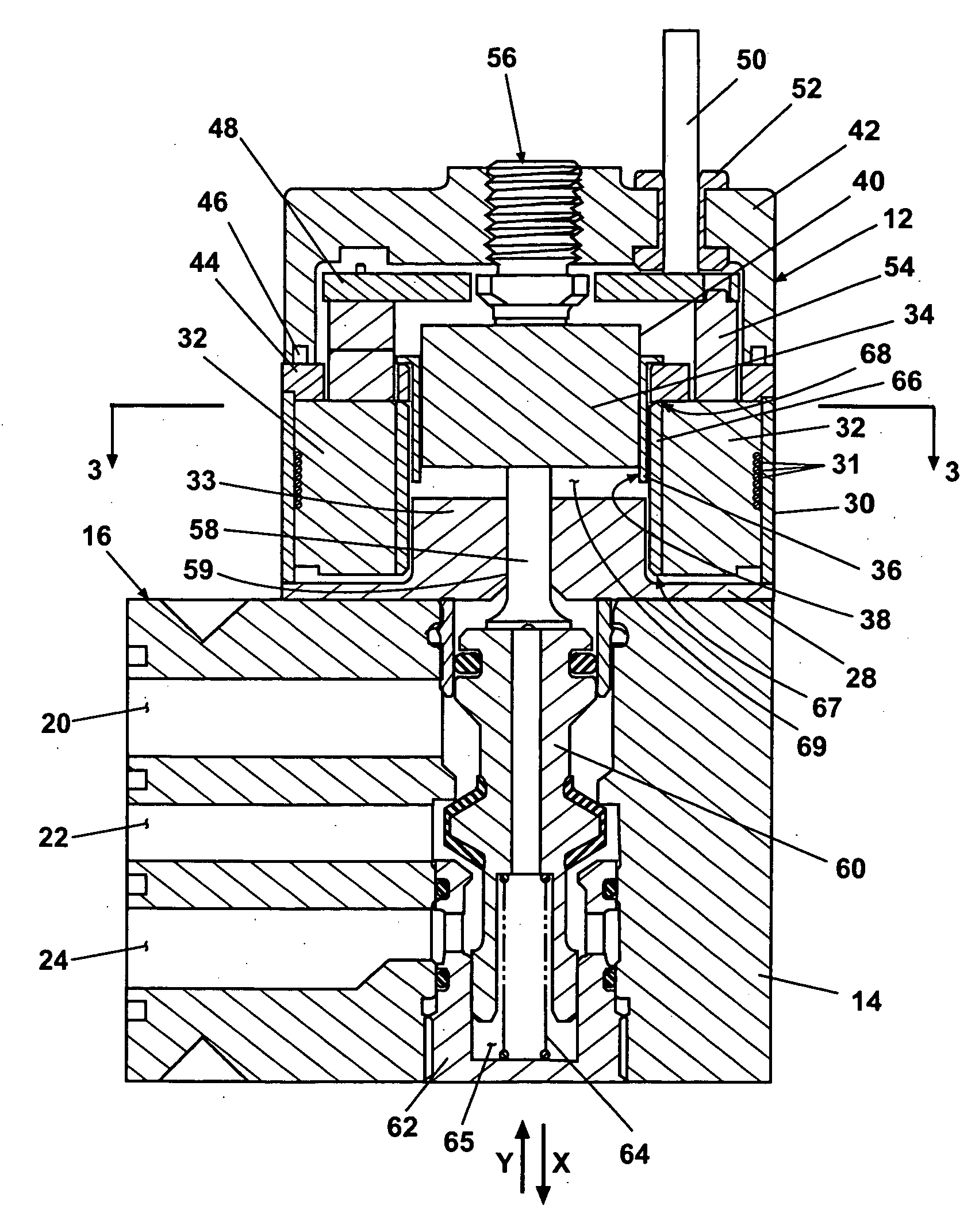
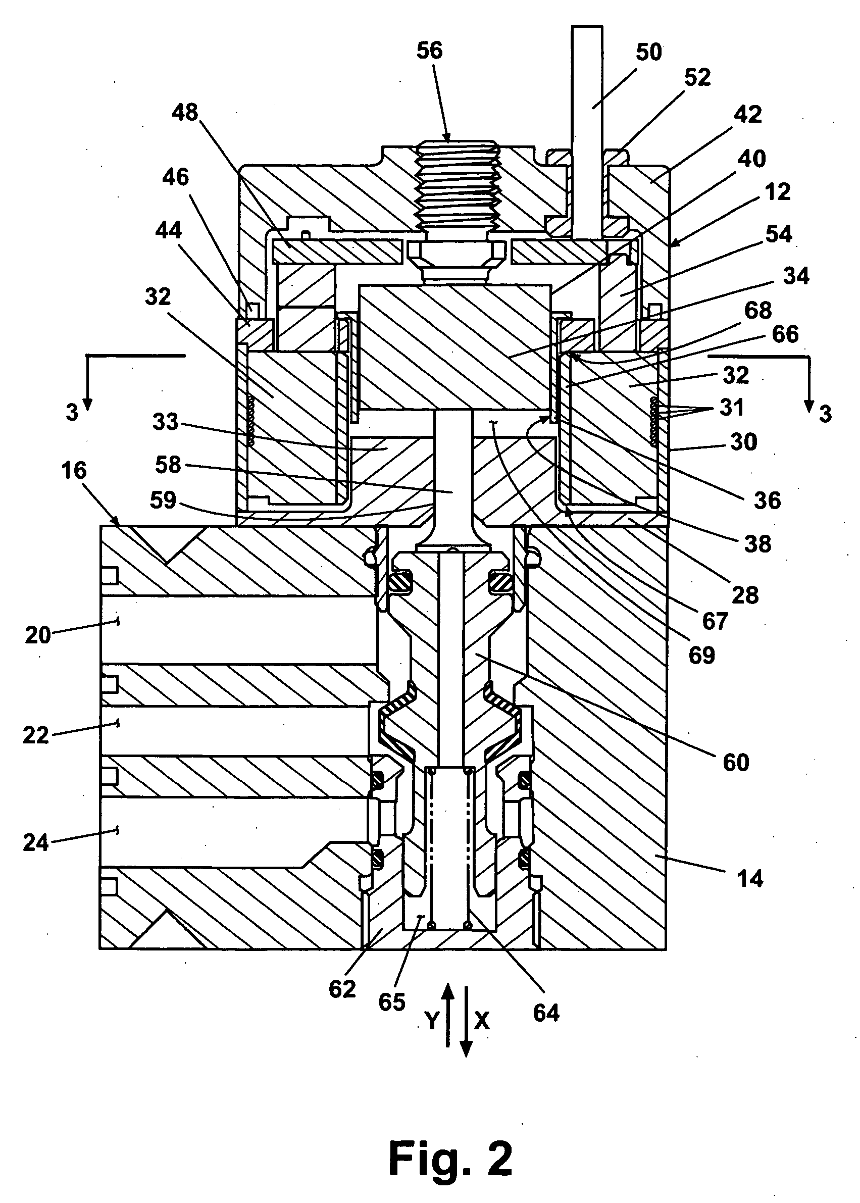
[0017] Referring next to FIG. 2, components of the solenoid 12 include a pole plate 28 which forms an interface between solenoid 12 and valve body 14 via valve body mounting face 16. A flux frame 30 formed generally at a perimeter of pole plate 28 provides an external limit for ind...


PUM


Abstract

A solenoid for an electromagnetically operated valve includes a bobbin having a substantially rectangular or elliptical cross section, a pole plate stationary with respect to the bobbin, and an armature slidable within the bobbin in response to a magnetic field generated by the coil through the pole plate. A coil wound around the bobbin has a rectangular cross section which on a short axis side includes a width W. A relation between width W and a virtual cylindrical iron core of diameter D having the same cross sectional area as an armature cross sectional area is expressed as D=(0.4 to 0.8) W. A ratio of a length A of a long axis side of the armature to a length B of a short axis side of the armature has a range between 3.1≦(A / B)≦4.5.

Description

CROSS-REFERENCE TO RELATED APPLICATIONS [0001] This application claims the benefit of U.S. Provisional Application Ser. No. 60 / 599,814 filed Aug. 6, 2004, the disclosure of which is incorporated herein by reference.FIELD OF THE INVENTION [0002] The present invention relates in general to solenoids and more specifically to solenoids used in conjunction with a valve to control operation of the valve. BACKGROUND OF THE INVENTION [0003] Electromagnetically operated valves are known which include a bobbin supporting a winding formed as a coil of wire. A stationary core or pole plate typically made of a conductive material such as iron is mounted adjacent to a center hole of the bobbin. A movable armature is slidably disposed within the aperture of the bobbin such that when electrical current is passed through the winding of the coil, the armature is induced to translate toward the stationary pole plate. This translation of the armature can be mechanically used to actuate a valve assembly...

Claims


Application Information

Patent Timeline
Patent Type & Authority Applications(United States)
IPC IPC(8): F15B13/044
CPCF16K11/044H01F7/1607F16K31/0675Y10T137/86622F16K31/06
Inventor NEFF, ROBERT H.JANSSEN, ERIC P.
Owner MAC VALVES INC
Why Eureka
Try Eureka