Tool for fluid filling and circulation during oilfield well tubing

a technology for oilfield wells and fluids, applied in the direction of fluid removal, drilling accessories, borehole/well accessories, etc., can solve the problems of high time required for its start-up, increased risk/cost tasks, and considerable turning of installation, so as to save a considerable amount of operational time and improve the cleaning, removal and transfer of solids.

Inactive Publication Date: 2006-02-09
BASSO ANTONIO CARLOS CAYETANO
View PDF1 Cites 24 Cited by
  • Summary
  • Abstract
  • Description
  • Claims
  • Application Information

AI Technical Summary

Benefits of technology

[0003] The supply of circulating fluid is performed as many times as required, without delay and simultaneously with the tubing, which facilitates sliding of the descending pipe.
[0126] It is noted that between the lower and upper pockets, aligned with respect to one another, a displaceable stopper (that prevents the displacement of the block plug placed on the upper pocket) associated with a hydraulic operating means.

Problems solved by technology

In addition, when this fluid circulates during drilling, in its way up the well / drilling column annular space, it carries over detritus produced by the action of the drill bit and deposits them on the surface.
However, if the contingency occurs while the circulation circuit is open or discontinued, the time required for its start-up is highly critical, and the ensuing problems typically require additional high risk / cost tasks.
But in the event of any contingencies, such as the blockage of the pipe at any lower section, so that the open upper end, where the circulation head must be threaded, is far from the work floor, installation turns considerably difficult, and contingent risks increase.
It is also known that, in addition to pipe blockage, the incorporation of fluid that produces a weak layer decreases the level and results in differential pressure loss over strong layers, increasing the possibility of spring occurrences.
Evidently, as no drilling mud circulates through the circuit, there will be clogging and / or well shutdown due to solid deposits.
If the cementation if flawed, it is more difficult to obtain accurate assessments that might lead to the abandonment of the well, and even of the field when the latter is exploratory.
In all cases, the presence of operators is required at the wellhead, with the risks involved in working with the pressurized circuit.
The most remarkable problem arising is that the fluid supply must invariably be discontinued and the circuit must be shut down in order to mount the cement head.
In this sense, it should be highlighted, for instance, that the valve change required to launch the block plug, the depression produced by the free-falling cement creates an undesirable entry of air to the circuit, that later makes flow and pressure readings more difficult, with undesirable volume returns after arrival of the block plug due to the compression of the confined air, which forces to keep the cement head closed.
When said pipe decompresses to perform the tasks subsequent to well finishing, a micro annular space is formed between the outer pipe wall and the body of the hardened cement that creates a communication between the layers, which may cause problems that might require highly complicated and costly supplementary repair works.
They are commonly used to contain fluids over rotational movements, are not capable of containing high pressures.

Method used


Image

  • Tool for fluid filling and circulation during oilfield well tubing
  • Tool for fluid filling and circulation during oilfield well tubing
  • Tool for fluid filling and circulation during oilfield well tubing

Examples


Embodiment Construction

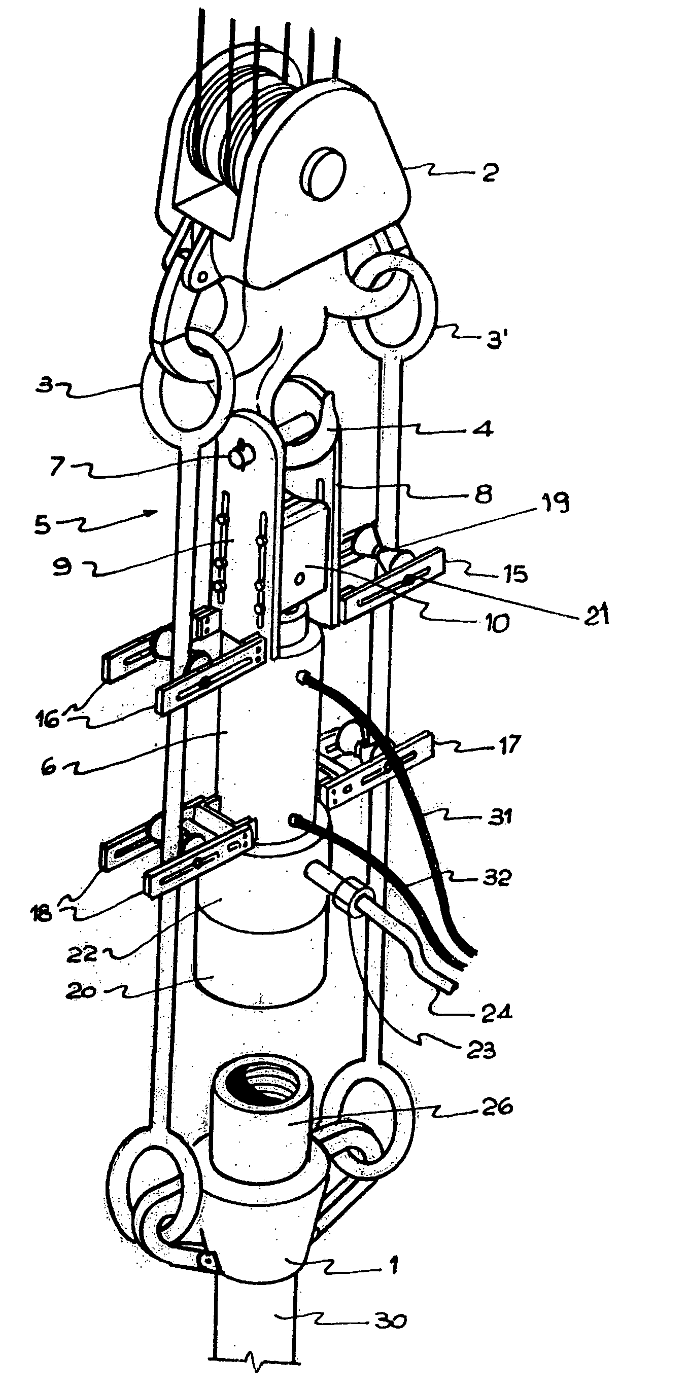
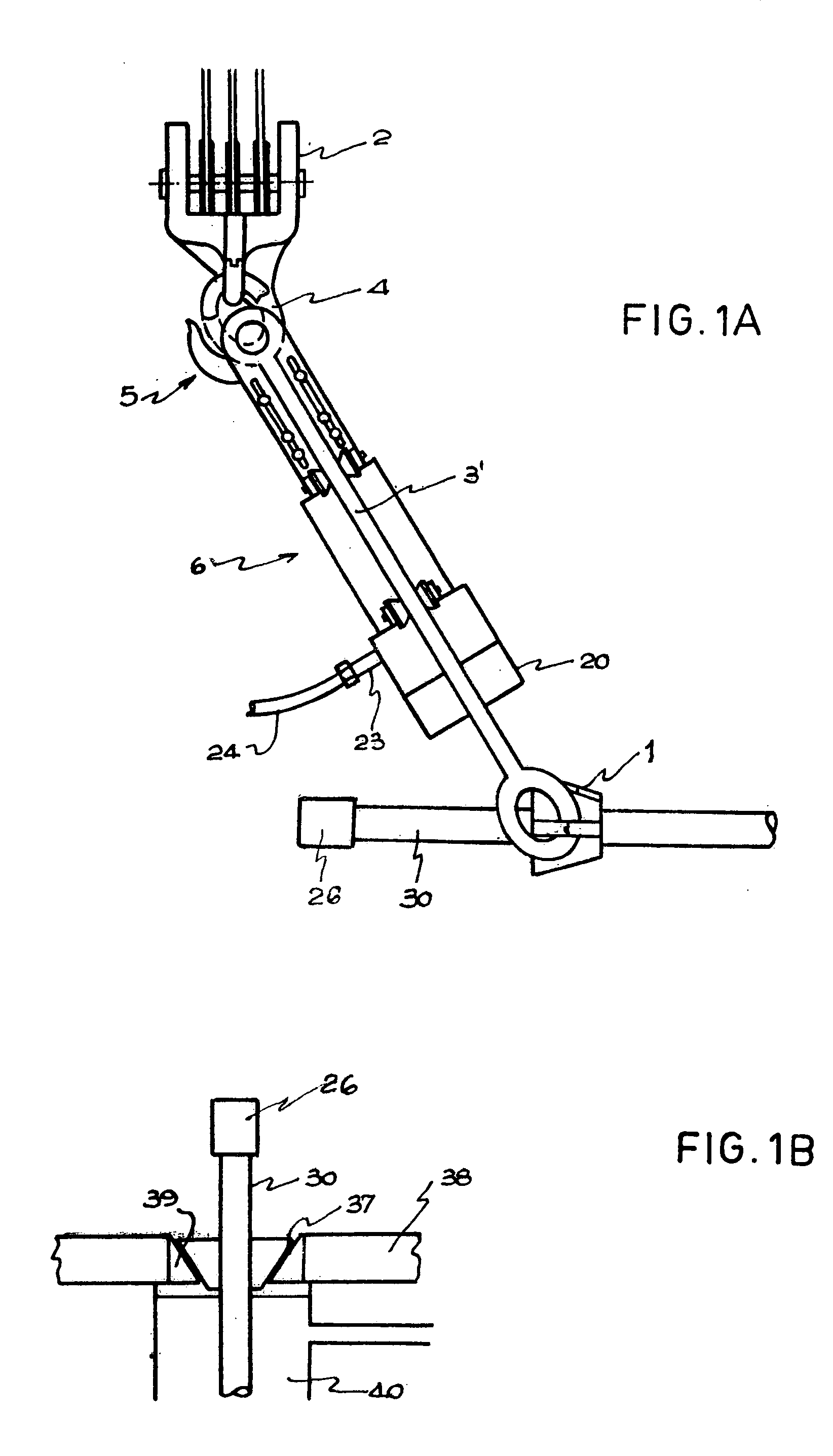
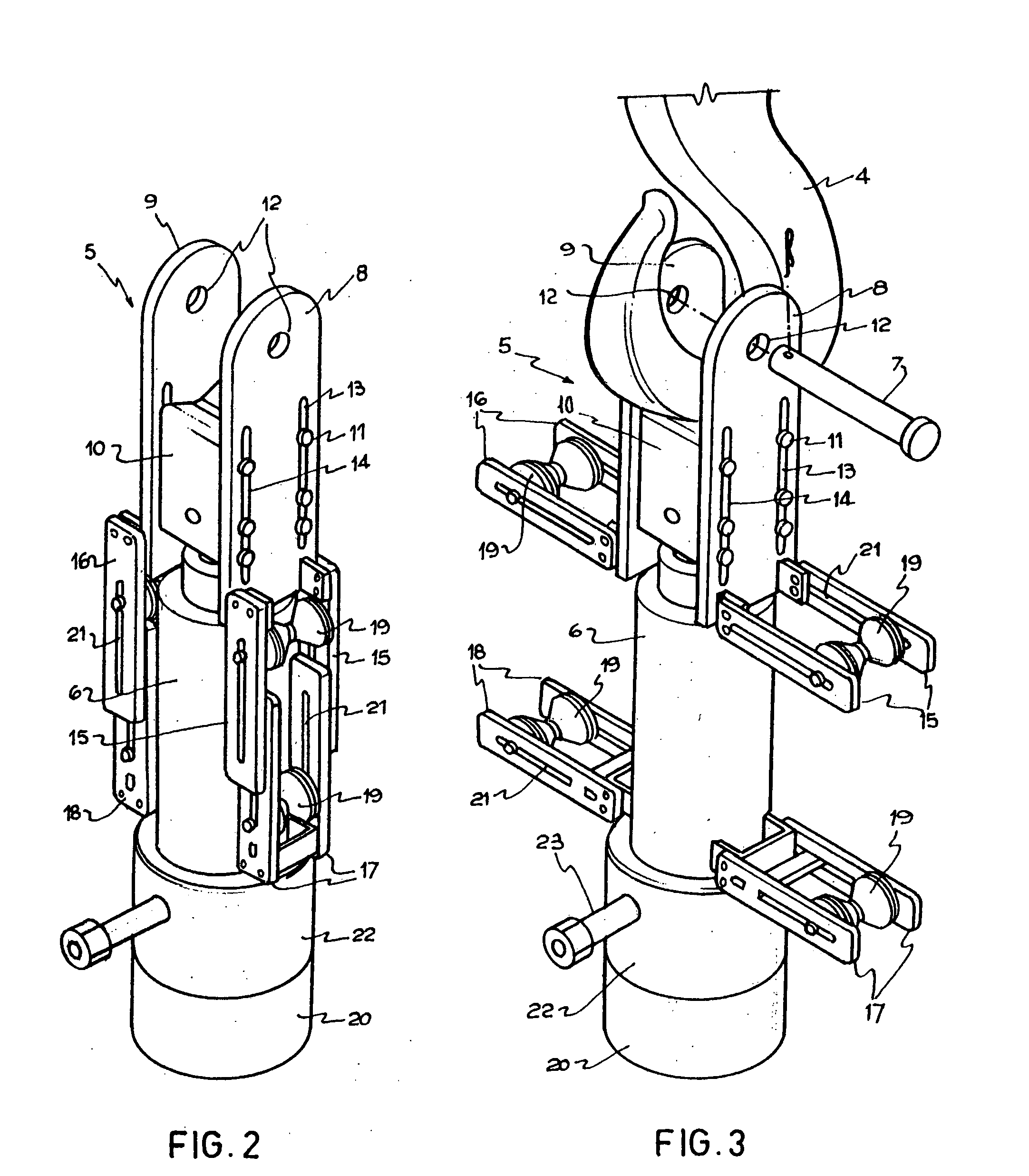
[0143] As can be appreciated from FIG. 1, the tool for filling and circulating the fluid during the tubing of oilfield wells of the present patent of invention has been especially designed to be intercalated between the elevating device (1) and the block (2), between the amelas (3 / 3′) (visible in FIG. 4) which link said pipe elevator (1) with said block (2) of the drilling equipment.

[0144] It should be noted that these elements (1 / 2 / 3 / 3′) are only schematically represented so as not to confuse the object of this invention, and that it is not subject to the characteristics or conditions featured by them and that are common to most drilling equipment.

[0145] In this preferred example, the tool of the invention operates between said amelas (3 / 3′), supported from hook (4) of the block, to which it is connected, in this case, through the support array (5).

[0146]FIG. 1 shows that the mounting of the tool of the invention does not affect the operation of the drilling equipment when takin...


PUM


Abstract

A tool designed to be used in vertical, horizontal or deviated wells with the aim of maintaining the tubed pipe filled with the drilling fluid supplied by the well, and of circulating said fluid through the well-pipe space, facilitating the sliding of the tubing and producing the cementation of said space when the pipe has been installed; capable of being intercalated with the drilling equipment between the block and the hanging elevating arangement that takes the tubes that are gradually coupled to make up the casing pipe. The tool of the invention is placed between the amelas that extend from the rig support to the adjacencies of the pipe elevating device of the drilling equipment, comprising a support array, responsible for positioning said tool hanging from the rig hook and aligned between the amelas; a positioning dynamic array, responsible for producing vertical upward and downward movements, which generate the matings or decouplings of the tool on the tubed pipe, and a packaging array through which, during the matings, a hermetic blockage self-adjustable elastic seal is established during the passage of well fluid towards the inside of the tubing pipe.

Description

[0001] It is the main object of this patent A TOOL FOR FLUID FILLING AND CIRCULATION DURING OILFIELD WELL TUBING, contemplated for use in vertical, horizontal or deviated wells, and conceived to stay installed in automatic operating conditions whenever required. [0002] More specifically, this invention contemplates a tool especially created to introduce fluids in the tubed piping, using the same drilling fluid that fills the well, and to circulate same through the well-pipe space, at any time during tubing, or to circulate cementation fluids when layer isolation or pipe anchorage to the assembly is required. [0003] The supply of circulating fluid is performed as many times as required, without delay and simultaneously with the tubing, which facilitates sliding of the descending pipe. [0004] In this way, an automatic and immediate solution is provided, particularly for cases in which the pipe must be deployed in narrow well sites and / or with fluid admission, where spontaneous obstruc...

Claims


Application Information

Patent Timeline
Patent Type & Authority Applications(United States)
IPC IPC(8): E21B43/00
CPCE21B19/02E21B33/05E21B21/02
Inventor BASSO, ANTONIO CARLOS CAYETANO
Owner BASSO ANTONIO CARLOS CAYETANO
Why Eureka
Try Eureka