Control device for vehicular drive system

a control device and drive system technology, applied in the direction of engine-driven generators, machines/engines, transportation and packaging, etc., can solve the problems of unfavorable drive system size, unfavorable drive system, and risk of deterioration of fuel economy of same drive system, so as to improve the fuel economy of the vehicle and further reduce the resonance phenomenon

Active Publication Date: 2006-02-09
TOYOTA JIDOSHA KK
View PDF5 Cites 34 Cited by
  • Summary
  • Abstract
  • Description
  • Claims
  • Application Information

AI Technical Summary

Benefits of technology

[0009] The present invention was made in view of the background art described above. It is therefore an object of the present invention to provide a control device for a vehicular drive system, which permit

Problems solved by technology

However, there is not known any power transmitting mechanism that is suitable for improving both of the fuel economy and the power transmitting efficiency.
This drive system requires the first electric motor to be large-sized with an increase of the required output of the engine, so that the second electric motor operated with the electric energy supplied from the first electric motor is also required to be large-sized, whereby the drive system tends to be unfavorably large-sized.
The same drive system also suffers from a risk of deterioration of the fuel economy during a high-speed r

Method used


Image

  • Control device for vehicular drive system
  • Control device for vehicular drive system
  • Control device for vehicular drive system

Examples


Embodiment Construction

[0054] Referring to the drawings, there will be described in detail the preferred embodiment of the present invention.

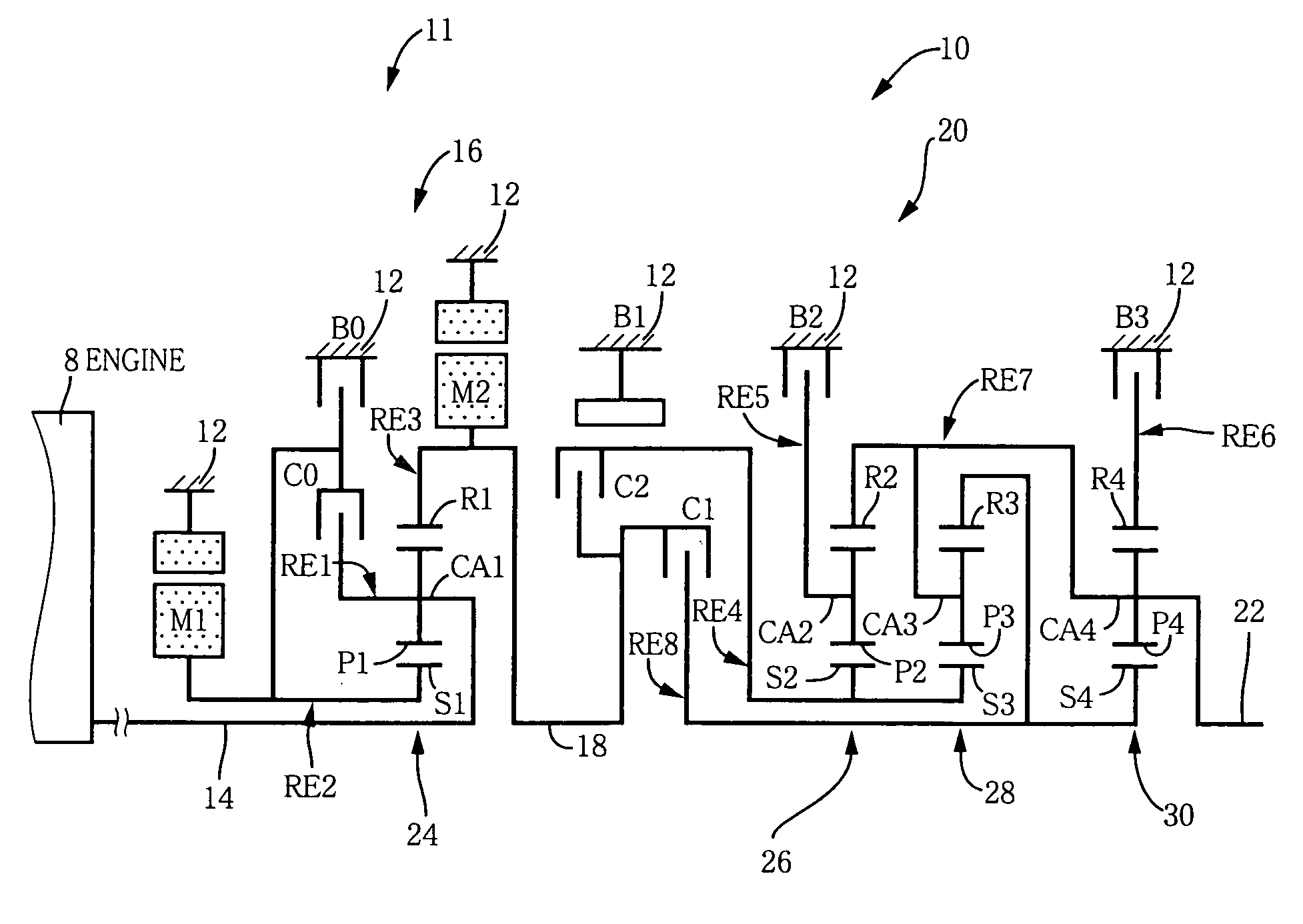
[0055] Reference is first made to the schematic view of FIG. 1 explaining a transmission mechanism 10 constituting a part of a drive system for a hybrid vehicle, which drive system is controlled by a control device according to one embodiment of this invention. The transmission mechanism 10 includes: an input rotary member in the form of an input shaft 14 disposed on a common axis in a transmission casing 12 functioning as a stationary member attached to a body of the vehicle; a continuously-variable transmission portion 11 connected to the input shaft 14 either directly, or indirectly via a pulsation absorbing damper (vibration damping device) not shown; a step-variable or multiple-step automatic transmission portion 20 interposed between and connected in series via a power transmitting member 18 (power transmitting shaft) to the continuously-variable transmission ...


PUM


Abstract

A control device for a vehicular drive system including (a) a differential mechanism operable to distribute an output of an engine (8) to a first electric motor and a power transmitting member, (b) a second electric motor disposed in a power transmitting path between the power transmitting member and a drive wheel of a vehicle, and (c) a differential-state switching device operable to place the differential mechanism selectively in one of a differential state in which the differential mechanism is operable to perform a differential function and a locked state in which the differential mechanism is not operable to perform the differential function, the control device including an engine-stop switching control portion operable to control the differential-state switching device to place the differential mechanism in the differential state, upon stopping of the engine, so that the engine speed can be rapidly lowered to zero by controlling the first electric motor in the differential state of the differential mechanism, so as to reduce a possibility of occurrence of a resonance phenomenon of the drive system and a resultant vibration of the vehicle when the engine is stopped.

Description

[0001] The present application is based on Japanese Patent Application No. 2004-229913 filed on Aug. 5, 2004, the content of which is incorporated herein by reference. BACKGROUND OF THE INVENTION [0002] 1. Field of the Invention [0003] The present invention relates in general to a control device for a vehicular drive system including an engine and a differential mechanism which functions as an electrically controlled differential device having a differential function, and more particularly to techniques for controlling the vehicular drive system upon stopping of the engine. [0004] 2. Description of Related Art [0005] There is known a drive system for a vehicle, which includes a differential mechanism arranged to distribute an output of an engine to a first electric motor and an output shaft, and a second electric motor disposed between the output shaft of the differential mechanism and drive wheels of the vehicle. Examples of this type of vehicular drive system include drive systems...

Claims


Application Information

Patent Timeline
IPC IPC(8): B60K17/00B60K6/365B60K6/445B60K6/547B60L50/16B60W10/00B60W10/02B60W10/04B60W10/06B60W10/08B60W10/10B60W10/11B60W10/115B60W20/00F02D17/00F02D29/00F02D29/02F16H61/02F16H61/68F16H61/684F16H61/686
CPCB60K6/365Y10S903/911B60K6/445B60K6/547B60W10/02B60W10/06B60W10/08B60W10/11B60W20/00Y02T10/6286Y02T10/6239Y10S903/945Y10S903/909Y10S903/946Y10S903/91Y10S903/917Y10S903/916Y10S903/918Y10S903/915B60K6/387Y02T10/62B60W20/10B60W20/40B60W20/30
Inventor TABATA, ATSUSHITAGA, YUTAKA
Owner TOYOTA JIDOSHA KK
Why Eureka
Try Eureka