Electrically conducting resin composition for fuel cell separator and fuel cell separator

a technology of electric conducting resin and fuel cell separator, which is applied in the direction of cell components, conductors, non-metal conductors, etc., can solve the problems of difficult to obtain sufficient mechanical characteristics for a fuel cell separator, and the mechanical properties of the electrically conducting resin composition containing the resin with low molecular weight are generally poor, and achieve excellent electrical conductivity, flexural strength, and flexural strain.

Inactive Publication Date: 2006-02-09
SHOWA DENKO KK
View PDF5 Cites 29 Cited by
  • Summary
  • Abstract
  • Description
  • Claims
  • Application Information

AI Technical Summary

Benefits of technology

[0022] Objects of the present invention are to provide an electrically conducting resin composition for a fuel cell separator which overcomes the aforementioned drawbacks of the conventional electrically conducting resin compositions, and to provide a fuel cell separator produced by molding this electrically conducting resin composition and having both of high electrical conductivity and flexural property.
[0037] The fuel cell separator of the present invention having the aforementioned constitutions is excellent in electrical conductivity, flexural strength, and flexural strain.

Problems solved by technology

Although various electrically conducting structures made of the respective conventional electrically conducting resin compositions disclosed in the foregoing patent Documents need to substantially increase the filling amount of electrically conducting filler such as carbonaceous materials in order to develop high electrical conductivity, this has resulted in the brittleness.
Thus, it is quite difficult to obtain sufficient mechanical characteristics required for a fuel cell separator such as flexural strength and flexural strain.
However, the mechanical property is generally poor in the electrically conducting resin composition containing the resin with low molecular weight.

Method used


Image

  • Electrically conducting resin composition for fuel cell separator and fuel cell separator
  • Electrically conducting resin composition for fuel cell separator and fuel cell separator

Examples


examples

[0088] Examples of the present invention will hereinafter be described in further detail, but it is not restricted thereto.

[0089] The materials used in the examples will be described hereinafter.

(Resin Component)

[0090] Resins 1 to 10, shown in Table 1, containing the components A and B were prepared as the resin component.

[0091] As the polypropylene resin of the component A, there were used SunAllomer PX900N (MFR=30), PX600N (MFR=7), PX400A (MFR=2), PW201N (MFR=0.4) manufactured by SunAllomer, Ltd.

[0092] The value of MFR is measured by the method in conformity with JIS K7210, specifically at a test temperature of 230° C. and a test load of 21.18 N (2.16 kg).

[0093] As the elastomer of the component C, there were used hydrogenated styrene-butadiene rubber (H-SBR) of Dynalon 1320P manufactured by JSR Corp. and styrene-ethylene / butylene-styrene block copolymer (SEBS) of Kraton G1652 manufactured by Kraton Polymers Japan, Ltd.

TABLE 1(% by mass)ComponentResin 1Resin 2Resin 3Resin...

examples 1 to 9

, Comparative Examples 1 to 3

[0100] The primary materials according to the resin component and the component B shown in Table 1 were placed in a Laboplastmill (trademark) (model 50C150 manufactured by Toyo Seiki Seisaku-Sho, Ltd.) and kneaded at a temperature of 200° C. and a rotation rate of 45 rpm for 7 minutes to obtain an electrically conducting resin composition. This composition was placed in a mold capable of molding a flat plate of 100 mm×100 mm (the thickness varies for each physical property test item), and then pressurized and heated using a 50 t compression molding machine (E-3013 manufactured by Nippon Engineering Co., Ltd.) at a temperature of 230° C. and a pressure of 15 MPa for 3 minutes after 3-minute preheating. Subsequently, the mold was cooled using a cooling press at a temperature of 25° C. and a pressure of 15 MPa for 2 minutes to obtain molded bodies of examples 1 to 9 and comparative examples 1 to 3. The composition of each molded body is shown in Tables 2 an...

example 10

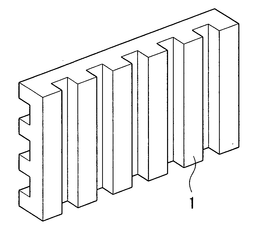
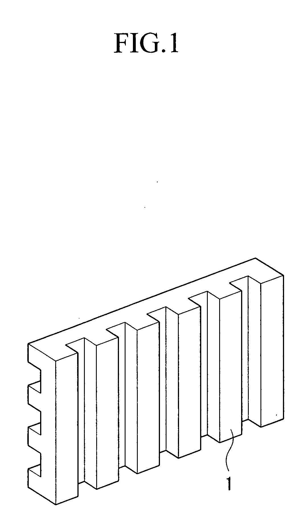
[0107] The aforementioned composition of the example 6 was placed in a mold capable of molding a flat plate of 100 mm×200 mm×1.5 mm in size with six through holes and a groove of 1 mm in width pitch and 0.5 mm in depth formed on either side thereof, and then pressurized and heated using the 50 t compression molding machine at a temperature of 230° C. and a pressure of 15 MPa for 3 minutes after 3-minute preheating. Subsequently, the mold was cooled using a cooling press at a temperature of 25° C. and a pressure of 15 MPa for 2 minutes to obtain a fuel cell separator. This fuel cell separator had a volume resistivity of 6.5 mΩ·cm and a thickness in the middle of 1.51 mm, and was very favorable.


PUM

PropertyMeasurementUnit
apparent viscosityaaaaaaaaaa
volume resistivityaaaaaaaaaa

Abstract

The present invention are to provide an electrically conducting resin composition for a fuel cell separator which overcomes the drawbacks of prior arts, and to provide a fuel cell separator produced by molding this electrically conducting resin composition and having both of high electrical conductivity and flexural property. The present invention employs an electrically conducting resin composition for a fuel cell including a component A of polypropylene resin whose melt flow rate is 0.01 or higher and 10 or lower and a component B of electrically conducting filler as well as a fuel cell separator made of the same.

Description

BACKGROUND OF THE INVENTION [0001] 1. Field of the Invention [0002] The present invention relates to an electrically conducting resin composition for a fuel cell separator and a fuel cell separator. In more detail, the present invention relates to an electrically conducting resin composition for a fuel cell separator including polypropylene resin whose melt flow rate (MFR) is 0.01 or higher and 10 or lower and electrically conducting filler and having both of high electrical conductivity and flexural property, and to a fuel cell separator made of the same. [0003] The present application claims priority on Japanese Patent Application No. 2004-157693 filed on May 27, 2004, the entire contents of which are incorporated herein by reference. The present application also claims the benefit of U.S. Provisional Application No. 60 / 577,189 filed on Jun. 7, 2004. [0004] 2. Description of Related Art [0005] There have conventionally been used mainly metallic materials and / or carbon materials, e...

Claims


Application Information

Patent Timeline
Patent Type & Authority Applications(United States)
IPC IPC(8): H01B1/24H01M8/02
CPCH01B1/24H01M8/0206H01M8/0213Y02E60/50H01M8/0226H01M2008/1095H01M8/0221
Inventor ARAI, TOSHIHIROSAKAMOTO, HIROSHIKOBAYASHI, TOMOAKI
Owner SHOWA DENKO KK
Why Eureka
Try Eureka