
Producing method for air bag

a production method and air bag technology, applied in the direction of catheters, angiography, diagnostic recording/measuring, etc., can solve the problems of air leakage, unusable sphygmomanometer, unusable cuff air bag, etc., to achieve the effect of producing an air bag easily and quickly

Inactive Publication Date: 2006-02-09
TK INC CO
View PDF1 Cites 10 Cited by
  • Summary
  • Abstract
  • Description
  • Claims
  • Application Information

AI Technical Summary

Benefits of technology

[0017] As a result, such jointing portion, being formed with a predetermined width along the planar direction of the sheet, can easily withstand a tensile stress acting in the planar direction of the sheet.
[0018] Therefore, even in case the air of a predetermined pressure is sealed inside to exert a strong force repeatedly from the interior to the exterior, the jointed portion can withstand, without showing a peeling, daily use over a prolonged period.
[0024] In the present invention, therefore, since the aforementioned jointed portion is placed in intermediate positions in the longitudinal direction of the mutually opposed two other sides present in a pair and such two other sides are then welded, the completed air bag has the jointed portion formed in the first step in the intermediate positions in the longitudinal direction of the other two sides. Thus, when the air bag is used with compressed air therein, the tensile stress in the planar direction acts substantially uniformly on the jointed portion, whereby such jointed portion can be prevented from a situation where only one side thereof is subjected to a large stress and the jointed portion scarcely shows peeling even after use over a prolonged period. As a result, the durability of the air bag can be further improved.
[0026] As a result, the invention allows to produce an air bag easily and promptly, in comparison with the prior case in which the sides of two sheets are respectively jointed by fusion.

Problems solved by technology

In the prior air bag for cuff produced in such manner, the air blown therein at the use of the sphygmomanometer is compressed to constantly exert a pressure acting from the interior of the bag to the exterior, so that the sealed joint in the entire periphery of the aforementioned resin sheets is constantly subjected to a stress for peeling the sealed joint, and, in case the welded bonding in such sealed joint is weaker in a portion than in other positions, a peeling may result in the use over years to cause air leakage from such portion, whereby the sphygmomanometer becomes no longer usable.
When the jointed portion is constantly subjected to a force in a direction for peeling off such jointed portion, since the portion jointed by welding does not have a very high adhesion strength because of a limited width thereof in the acting direction of the stress, the jointed portion shows a gradual peeling in time from a lower end thereof, thereby resulting in a leakage of the compressed air to the exterior and becoming unusable as the cuff air bag.

Method used


Image

  • Producing method for air bag
  • Producing method for air bag
  • Producing method for air bag

Examples


Embodiment Construction

[0035] In the following, a process for producing an air bag for a cuff of a sphygmomanometer will be explained in detail, with reference to accompanying drawings, as an embodiment of the air bag of the present invention applied to such cuff air bag of the sphygmomanometer.

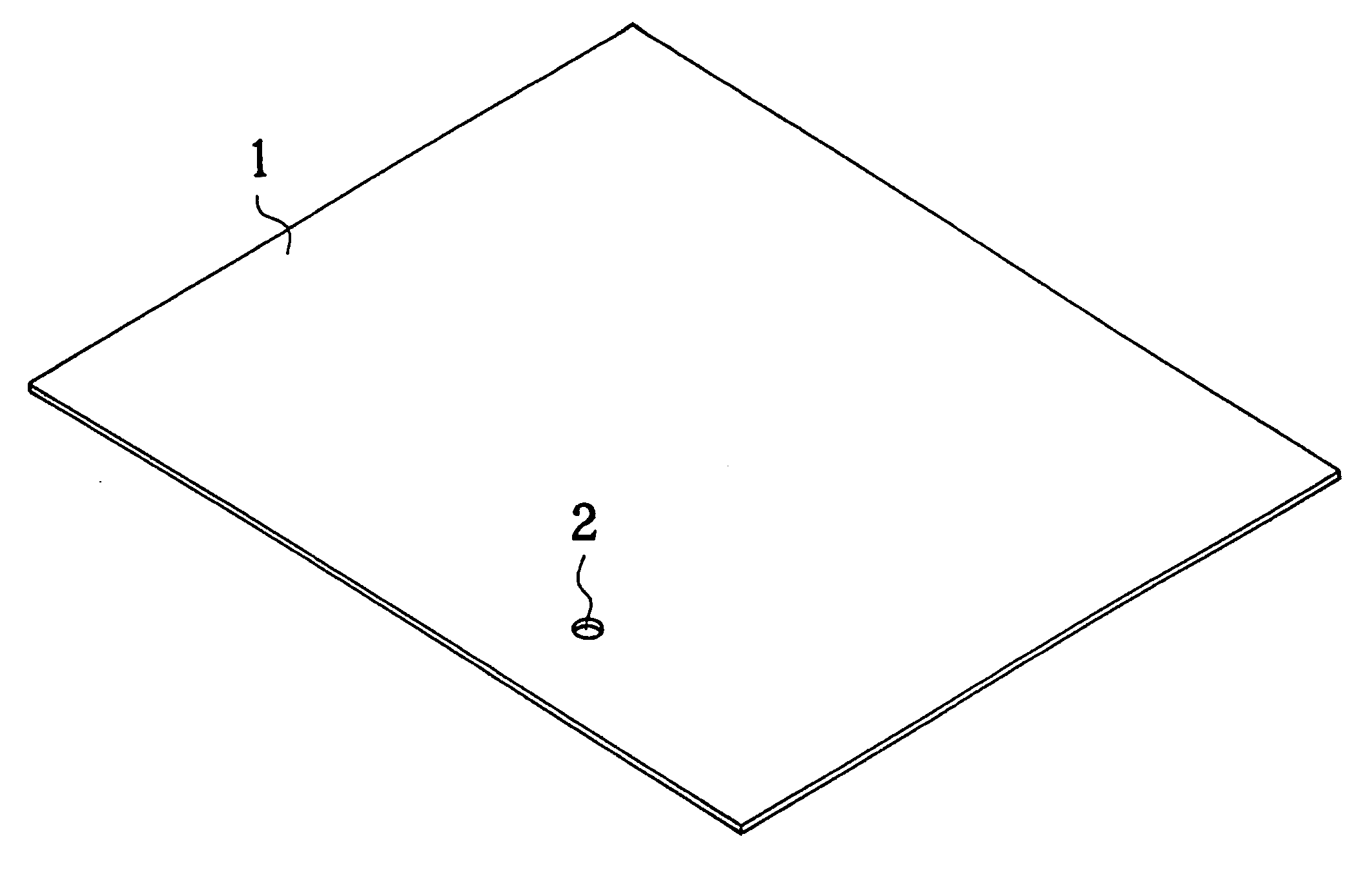
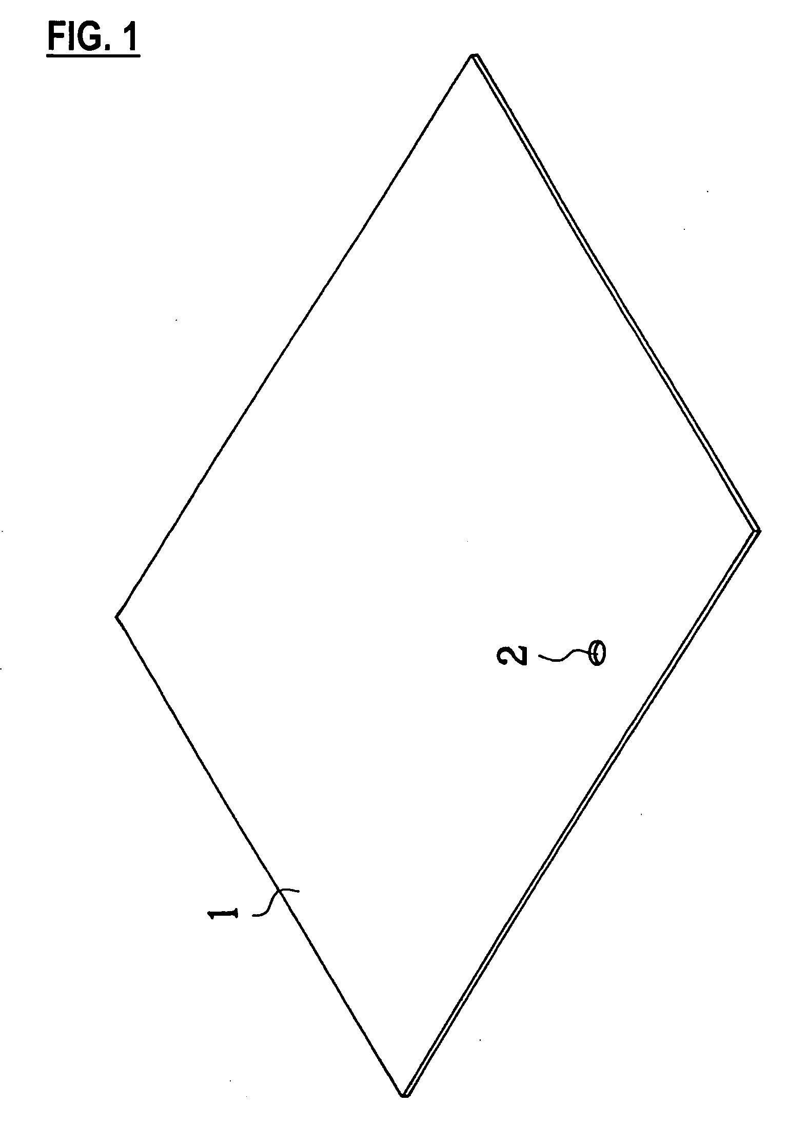
[0036] At first, as shown in FIG. 1, a PVC (polyvinyl chloride) sheet 1 of a rectangular shape is prepared, and a mounting hole 2 for mounting an air tube connector (cf. FIG. 2) is formed in a predetermined position.

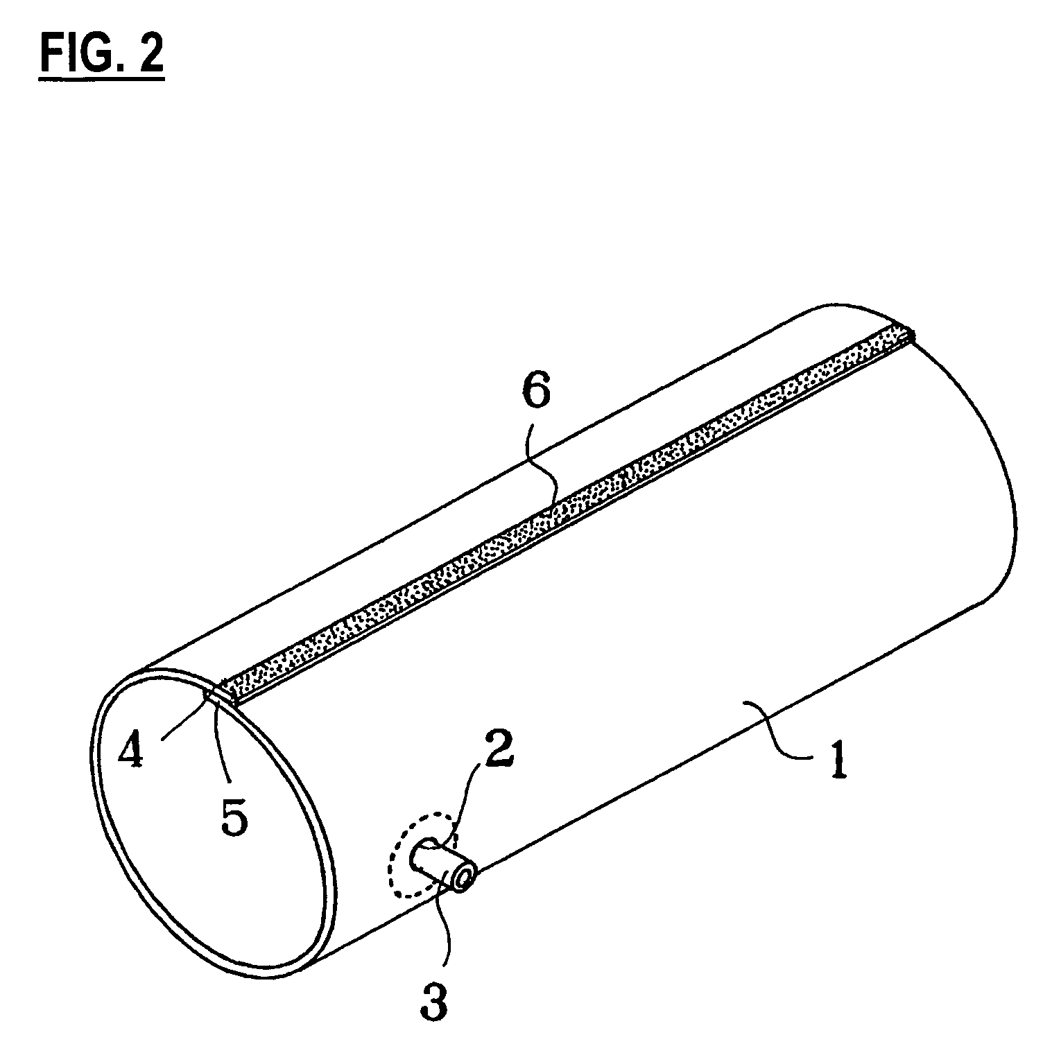
[0037] Then, after an air tube connector 3 is mounted for example by welding on the mounting hole 2 of the PVC sheet 1, edge portions 4, 5 of two opposed sides of the resin sheet 1 are superposed and jointed in such a manner that an external surface of an edge portion 5 comes into contact with an internal surface of the other edge portion 4, and such jointed portion is welded by a high frequency welder to form the PVC sheet into a tubular shape. In the drawings, a numeral 6 indicates the jointed porti...


PUM

PropertyMeasurementUnit
widthaaaaaaaaaa
sizeaaaaaaaaaa
sizeaaaaaaaaaa

Abstract

The method of the invention includes a step of jointing, in a sheet formed in a rectangular shape, end portions of a pair of mutually opposed two sides in such a manner as to form a jointed portion of a predetermined width along a planar direction of the sheet. In the rectangular sheet 1, a pair of mutually opposed two end portions 4, 5 are jointed by a joint portion formed along the planar direction of the sheet.

Description

BACKGROUND OF THE INVENTION [0001] The present invention relates to an improvement on a method for producing an air bag. [0002] A sphygmomanometer is generally equipped with an air bag constituting a cuff to be wound on for pressurizing an arm of an inspected person at a blood pressure measurement. [0003] Such air bag, for use as a cuff (arm band) of a sphygmomanometer, has been produced by superposing two rectangular resin sheets and sealing the entire periphery for example by welding. [0004] In the prior air bag for cuff produced in such manner, the air blown therein at the use of the sphygmomanometer is compressed to constantly exert a pressure acting from the interior of the bag to the exterior, so that the sealed joint in the entire periphery of the aforementioned resin sheets is constantly subjected to a stress for peeling the sealed joint, and, in case the welded bonding in such sealed joint is weaker in a portion than in other positions, a peeling may result in the use over ...

Claims


Application Information

Patent Timeline
Patent Type & Authority Applications(United States)
IPC IPC(8): B27N3/08B29C65/06A61B5/02
CPCA61B5/02233B29C66/4742B29C53/40B29C65/02B29C66/1122B29C66/43121B29C66/4322B29D22/02B29L2022/027B29L2023/001B29L2031/7148B29L2031/753B29C53/385B29C65/04B29C66/112B29C66/131B29C66/3452B29C66/47421B29C66/53243B29C66/53247B29C66/53262B29C66/71B29K2027/06
Inventor KAWAMURA, TAKAO
Owner TK INC CO
Learn More