
Abnormal voltage detector apparatus for detecting voltage abnormality in assembled battery

Inactive Publication Date: 2006-02-09
PANASONIC EV ENERGY CO LTD
View PDF3 Cites 94 Cited by
  • Summary
  • Abstract
  • Description
  • Claims
  • Application Information

AI Technical Summary

Benefits of technology

[0012] An essential object of the present invention is therefore to provide an abnormal voltage detector apparatus for use in an assembled battery including a plurality of battery blocks connected in series, capable of detecting a voltage abnormality of the assembled battery with a high accuracy and reliability, as compared with the prior art.
[0029] Accordingly, the abnormal voltage detector apparatus for use in the assembled battery according to the present invention can detects the voltage abnormality of the assembled battery with high accuracy and reliability, as compared with the prior art. Because it generates each of abnormality detecting signals containing information about whether or not each of the battery blocks is in a normal state, calculates the time ratio of a time interval, for which the assembled battery is in a voltage abnormality state, to a predetermined time interval, based on the abnormality detecting signals, and detects the voltage abnormality of the assembled battery based on the calculated time ratio. Then the abnormal voltage detector apparatus for use in the assembled battery according to the present invention relatively changes either one of each of the battery measuring voltages of each battery block and the reference voltage, generates each of the abnormality detecting signals by comparing each of battery measuring voltages with the reference voltage, and can detect whether or not the detecting part operates normally based on the abnormality detecting signals.

Problems solved by technology

The abnormal voltage detector apparatus detects voltage abnormality in the assembled battery.

Method used


Image

  • Abnormal voltage detector apparatus for detecting voltage abnormality in assembled battery
  • Abnormal voltage detector apparatus for detecting voltage abnormality in assembled battery
  • Abnormal voltage detector apparatus for detecting voltage abnormality in assembled battery

Examples


first preferred embodiment

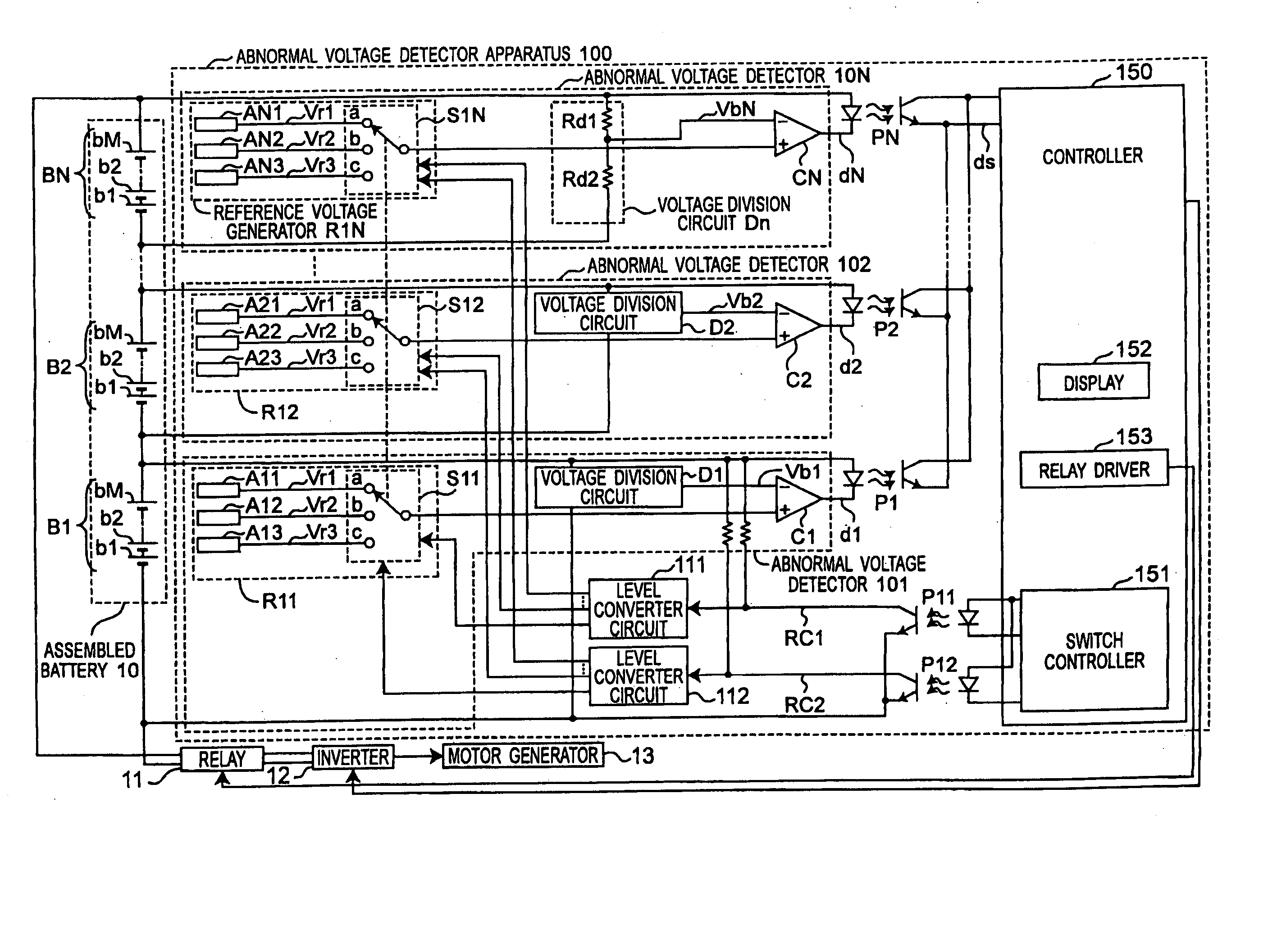
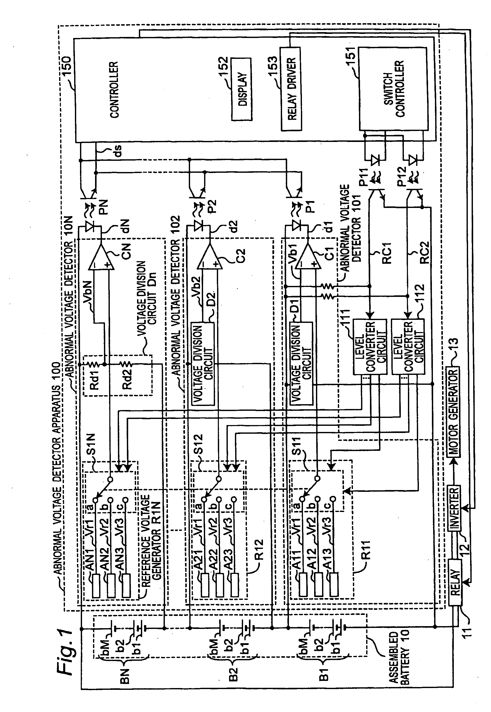
[0051] Referring to FIGS. 1 to 10, an abnormal voltage detector apparatus 100 according to a first preferred embodiment of the present invention will be described.

[0052]FIG. 1 is a block diagram showing a schematic configuration of the abnormal voltage detector apparatus 100 for use in the assembled battery according to a first preferred embodiment of the present invention. In FIG. 1, reference numeral 100 denotes an abnormal voltage detector apparatus, reference numeral 10 denotes an assembled battery, reference numeral 11 denotes a relay, reference numeral 12 denotes an inverter, and reference numeral 13 denotes a motor generator. The abnormal voltage detector apparatus 100, the assembled battery 10, the relay 11, the inverter 12, and the motor generator 13 are all installed in an electric vehicle. The DC power of the assembled battery 10 is converted into AC power by the inverter 12, and the AC power drives the motor generator 13, so that the electric vehicle runs. The relay 11 ...

second preferred embodiment

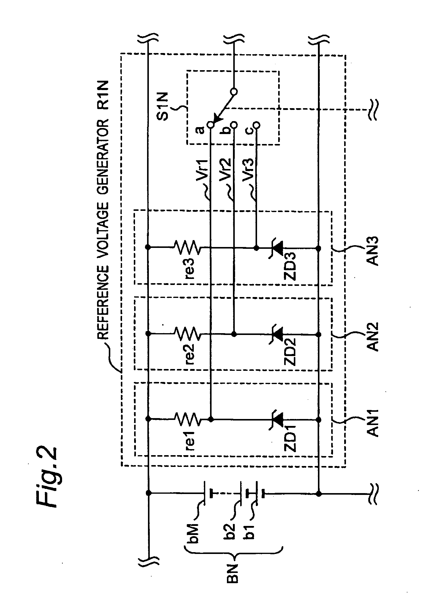
[0077] Referring to FIGS. 3 to 7, and FIG. 11, an abnormal voltage detector apparatus 300 according to a second preferred embodiment of the present invention will be described. FIG. 11 is a block diagram showing a schematic configuration of the abnormal voltage detector apparatus 300 for use in the assembled battery 10 according to the second preferred embodiment of the present invention. In FIG. 11, components common to those shown in FIG. 1 are designated by common numerals, and their descriptions are omitted. Each of the reference voltage generators R11 to R1N of the abnormal voltage detector apparatus 100 according to the first preferred embodiment includes the three reference voltage sources to generate the first, the second, and the third reference. According to a second preferred embodiment, another configuration of each abnormal voltage detector for generating the first, the second, and the third reference voltages will be shown.

[0078] In FIG. 11, reference numeral 300 deno...

third preferred embodiment

[0085] Referring to FIGS. 3 to 7 and FIG. 12, an abnormal voltage detector apparatus 400 according to a third preferred embodiment of the present invention will be described. FIG. 12 is a block diagram showing a schematic configuration of the abnormal voltage detector apparatus 400 for use in the assembled battery 10 according to the third preferred embodiment of the present invention. In FIG. 12, components common to those shown in FIG. 1 are designated by common numerals, and their descriptions are omitted. The abnormal voltage detector apparatus 400 has such a configuration that the abnormal voltage detector apparatus 100 according to the first preferred embodiment has an additional function of detecting whether or not an abnormal voltage detection function operates normally (also referred to as “a function of checking the abnormality detecting function”).

[0086] In FIG. 4, reference numeral 400 denotes the abnormal voltage detector apparatus, reference numeral 10 denotes the ass...


PUM


Abstract

An abnormal voltage detector apparatus is provided for an assembled battery including a plurality of battery blocks connected in series to each other. In the abnormal voltage detector apparatus, a detecting part detects whether or not each of the battery blocks is in a voltage abnormality state by comparing either one of a voltage of each battery block and each battery measuring voltage, that is a voltage lowered from the voltage of each battery block, with a predetermined reference voltage, generates each of abnormality detecting signals containing information about a detected result, calculates a time ratio of a time interval, for which the assembled battery is in a voltage abnormality state, to a predetermined time interval, based on the abnormality detecting signals, and detects a voltage abnormality of the assembled battery based on a calculated time ratio.

Description

BACKGROUND OF THE INVENTION [0001] 1. Field of the Invention [0002] The present invention relates to an abnormal voltage detector apparatus for use in an assembled battery, and in particular, to an abnormal voltage detector apparatus for detecting voltage abnormality in the assembled battery. [0003] 2. Description of the Related Art [0004] A sealed nickel-metal hydride battery (hereinafter referred to as a “nickel-hydrogen battery”) is excellent in basic characteristics, such as energy density, output density and cycle life. Accordingly, in recent years, attention has been given to such a nickel-hydrogen battery as a power source for motors and as a drive source for various kinds of loads in electric vehicles, such as pure electric vehicles (PEVS) and hybrid electric vehicles (HEVs). Development has been thus advancing to make such a nickel-hydrogen battery practical. [0005] When the nickel-hydrogen battery is used as a power source for electric vehicles, a total voltage of approxim...

Claims


Application Information

Patent Timeline
IPC IPC(8): H02J7/00
CPCG01R19/16542H02J7/0026H02J7/0021Y02T10/7055Y02T10/70H02J7/005H02J7/00302H02J7/00306H02J7/0013H02J7/0048
Inventor YUDAHIRA, HIROFUMINAKANISHI, TOSHIAKI
Owner PANASONIC EV ENERGY CO LTD
Learn More