Precision non-contact digital switch

a digital switch, non-contact technology, applied in the direction of electronic switching, pulse technique, electrical apparatus, etc., can solve the problems of low switching point accuracy, increased assembly mechanical tolerances required to achieve prescribed accuracy, system failures, etc., to reduce assembly mechanical tolerances, reduce magnetic field variation, and improve switch point accuracy

Inactive Publication Date: 2006-02-09
HONEYWELL INT INC
View PDF8 Cites 6 Cited by
  • Summary
  • Abstract
  • Description
  • Claims
  • Application Information

AI Technical Summary

Benefits of technology

[0011] It is still a further aspect of the present invention to provide for a non-contact digital switch apparatus, including methods and systems thereof, with improved accuracy of the switch point and / or decreased assembly mechanical tolerances to achieve a prescribed accuracy.
[0012] The aforementioned aspects of the invention and other objectives and advantages can now be achieved as described herein. A switch apparatus, system and method are disclosed herein, including one or more magnetic sensing elements that follow a travel path thereof, and a plurality of permanent magnets located in a mirrored configuration about the travel path. Such a configuration permits a magnetic field variation associated with the permanent magnets and the magnetic sensing element to be reduced with respect to the magnetic sensing element and the permanent magnets position tolerances, thereby generating a reduced magnetic field variation thereof which improves switching accuracy. A signal processing module can also be provided, which includes a signal conditioning circuit associated with a microprocessor. The signal conditioning circuit receives data from one or more of the magnetic sensing elements for signal conditioning and outputs data to the microprocessor for processing thereof.
[0013] The magnetic sensing element(s) can be configured as, for example, a Hall-effect element, a GMR (Giant Magnetoresistive) element, an AMR (Anisotropic Magnetoresistive) element and / or another type of electric transducer. The permanent magnets can be arranged in a configuration of four permanent magnets, wherein two of the four permanent magnets are located on one side of the travel path and two remaining of the four permanent magnets are located on the opposite side of the travel path. By adding additional magnets mirrored about the magnetic sensing element (e.g., a Hall-effect element, GMR, AMR, etc.) travel path, the magnetic field variation can be reduced with respect to the magnet to magnetic sensing element assembly position tolerances. The reduced magnetic field variation can therefore improve switching accuracy.

Problems solved by technology

This is a benefit because over time contacts can degrade and cause system failures.
One of the problems with conventional switching devices employing such magnetic sensing elements is that these types of devices are very sensitive to magnet and magnetic sensing element tolerances, which results in a low accuracy at the switching point and / or increased assembly mechanical tolerances required to achieve prescribed accuracies.

Method used


Image

  • Precision non-contact digital switch
  • Precision non-contact digital switch
  • Precision non-contact digital switch

Examples


Embodiment Construction

[0020] The particular values and configurations discussed in these non-limiting examples can be varied and are cited merely to illustrate at least one embodiment of the present invention and are not intended to limit the scope of the invention.

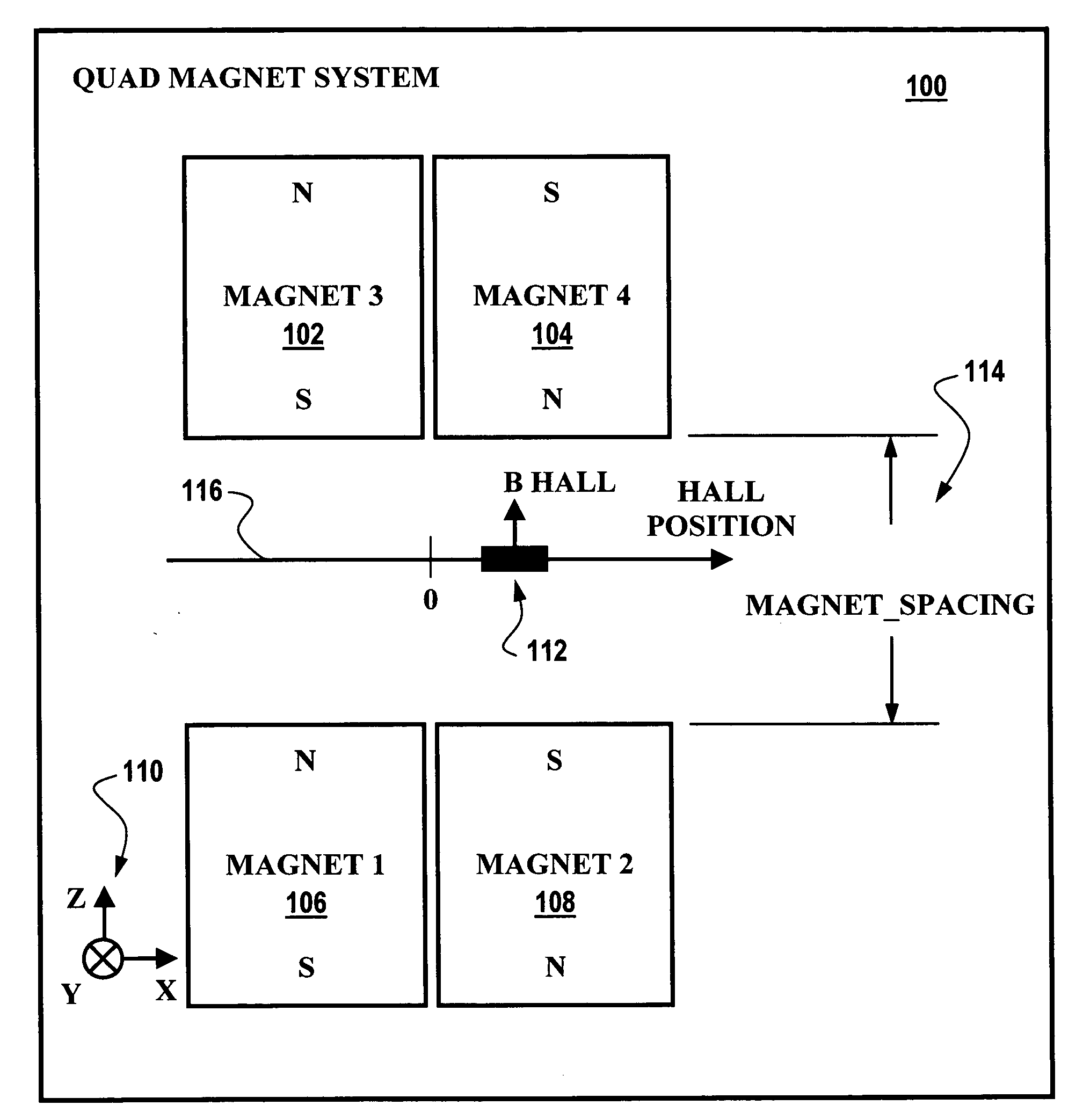
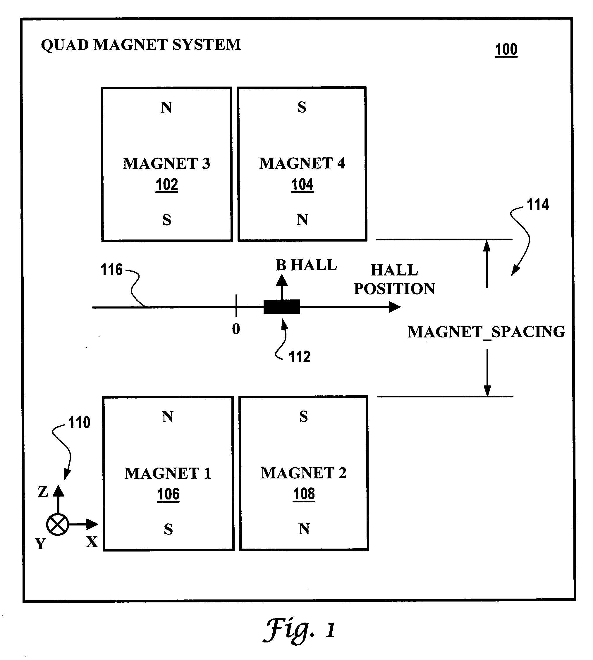
[0021]FIG. 1 illustrates a block diagram of quad magnet system 100, which can be implemented in accordance with a preferred embodiment. System 100 can be implemented in the context of a non-contact digital switch. System 100 can be configured to include one or more magnetic sensing element(s) 112 that follows a travel path thereof, which is indicated by arrow 116. A plurality of permanent magnets 102, 104, 106, 108 can be located in a mirrored configuration about the travel path indicated by arrow 116, such that the magnetic field variation associated with permanent magnets 102, 104, 106, 108 and the magnetic sensing element 112 can be reduced with respect to magnetic sensing element 112 and permanent magnets 102, 104, 106, 108 position toler...


PUM


Abstract

A switch apparatus, system and method are disclosed herein, including one or more magnetic sensing elements that follow a travel path thereof, and a plurality of permanent magnets located in a mirrored configuration about the travel path. Such a configuration permits a magnetic field variation associated with the permanent magnets and the magnetic sensing element to be reduced with respect to the magnetic sensing element and the permanent magnets position tolerances, thereby generating a reduced magnetic field variation thereof which improves switching accuracy. A signal processing module can also be provided, which includes a signal conditioning circuit associated with a microprocessor.

Description

TECHNICAL FIELD [0001] Embodiments are generally related to switching methods and systems. Embodiments are also related magnetic sensing elements, such as Hall-effect, GMR (Giant Magnetoresistive) and AMR (Anisotropic Magnetoresistive) elements. Embodiments are additionally related signal processing electronics and permanent magnets. BACKGROUND OF THE INVENTION [0002] Switching devices are utilized in a variety of industrial, commercial and consumer applications, including for example, automotive and aerospace application, along with including navigation, position sensing, current sensing, vehicle detection, and rotational displacement. Many switches rely upon magnetic sensing elements, such as Hall-effect, GMR (Giant Magnetoresistive) and AMR (Anisotropic Magnetoresistive) elements. [0003] There are many types of magnetic sensing devices, but essentially they all provide at least one output signal that represents the magnetic field sensed by the device. The Earth, magnets, and elec...

Claims


Application Information

Patent Timeline
Patent Type & Authority Applications(United States)
IPC IPC(8): H01H9/00
CPCH03K17/97H03K17/9517
Inventor BUSCH, NICHOLAS F.
Owner HONEYWELL INT INC
Why Eureka
Try Eureka