Electromagnetic actuating device

a technology of actuating device and actuating chamber, which is applied in the direction of braking system, electric welding apparatus, and electromagnet, etc., can solve the problems of unfavorable geometric profile deformation, and increasing the number so as to reduce the risk of lack of sealing, reduce the risk of cavities and pores, and reliable and mechanical stability

Inactive Publication Date: 2006-02-09
ETO MAGNETIC GMBH
View PDF7 Cites 24 Cited by
  • Summary
  • Abstract
  • Description
  • Claims
  • Application Information

AI Technical Summary

Benefits of technology

[0022] Since the present invention gives rise, in a particularly reliable and mechanically stable manner, to a connection interface between the connection mating elements which is low in cavities and pores, and thus the risk of lack of sealing is minimized, the present invention is particularly preferably suitable for electromagnetic

Problems solved by technology

However, traditional methods for manufacturing the magnet frame 12 consisting of core, intermediate section and yoke lead to undesirable deformations of the geometric profile at the critical transition region 28, as shown in FIG. 3 in respect of a conventional manufacturing process.
However, in the case of droplet-based MIG hard facing welding, on account of the very high arc temperatures there is the risk that the frustoconical profiles will be significantly changed thereby, as can be seen in FIG. 3.
A further disadvantage is that an increased number of cavities and pores are produced by the MIG hard facing welding process.
These give rise to the risk of lack of sealing in the region of the intermediate section 16, and also to the risk of a fatigue fracture of the magnet frame.
A further disadvantage of the conventional manufacturing method summarized above is that relatively long process times of typically approximately 30 seconds are required for the hard facing welding (build-up welding) proce

Method used


Image

  • Electromagnetic actuating device
  • Electromagnetic actuating device
  • Electromagnetic actuating device

Examples


Embodiment Construction

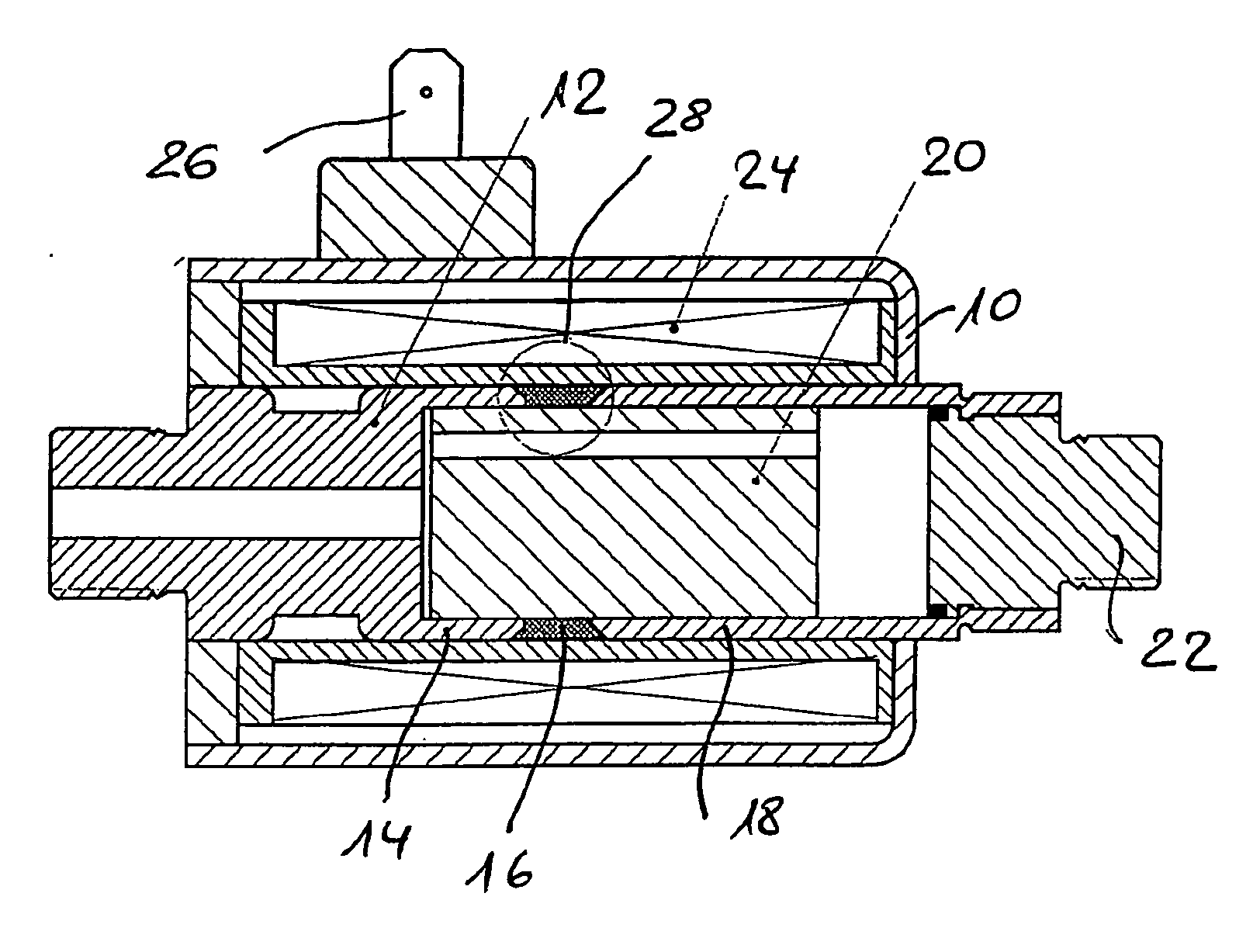
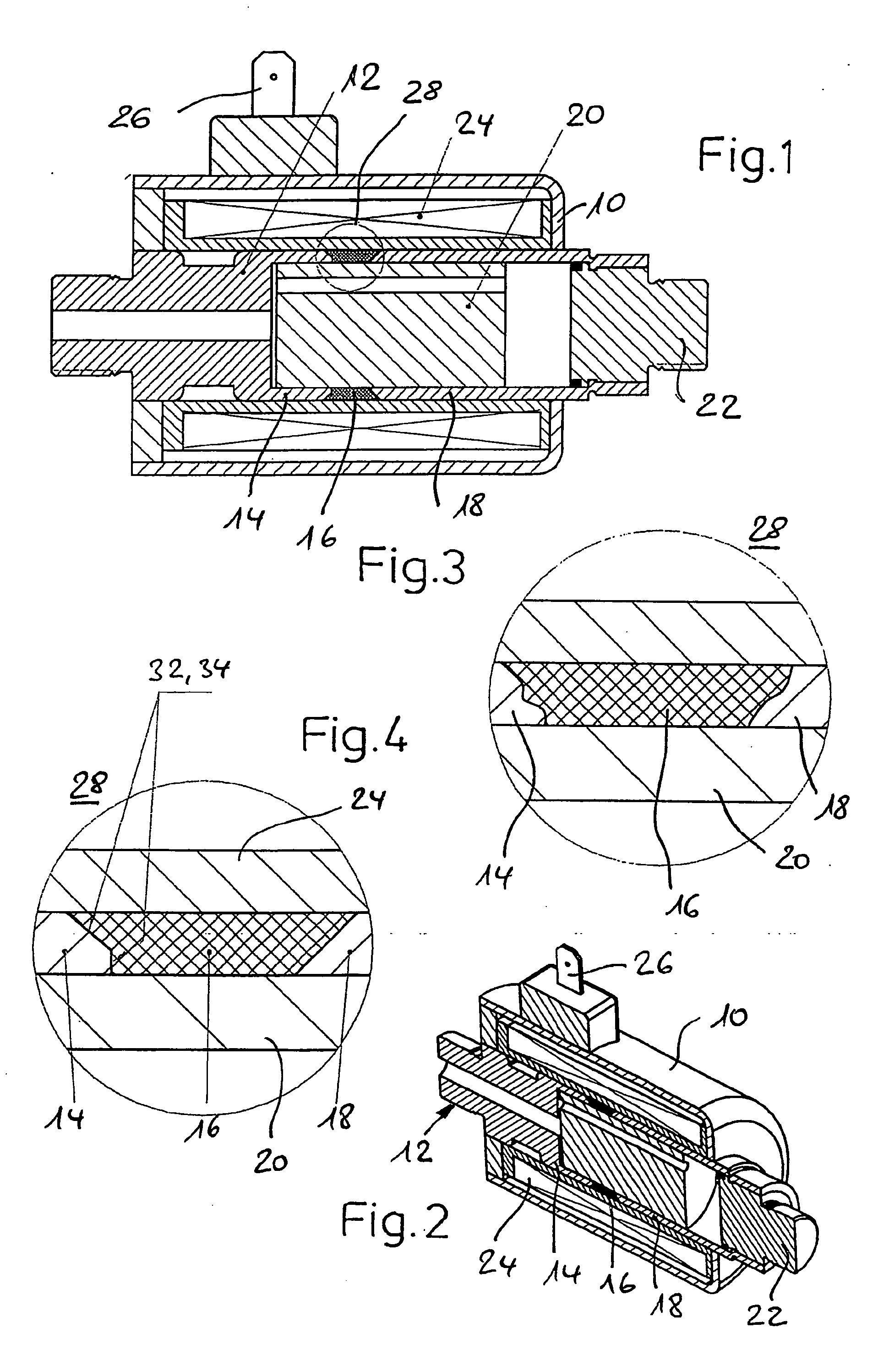
[0031] Based on the schematic representation described above of an electromagnetic actuator as shown in FIG. 1, FIG. 2 and the problems of deformation of the (in this case originally frustoconical) core and yoke geometry following application of the intermediate section 16 by hard facing welding (build-up welding), FIG. 4 shows, analogously to the diagram in FIG. 3, that as a result of the friction welding method the core-side frustoconical geometry comprising frustoconical section 32 and flat annular section 34 and the pure frustoconical shape of the yoke section 18 remain virtually non-deformed and thus unchanged, and thus the originally determined magnetic properties predefined by the frustoconical shape are fully retained. (In FIG. 4, the frustoconical profile of section 32 merges in a truncated manner into the flat annular section 34, which lies in a plane perpendicular to the axial direction.)

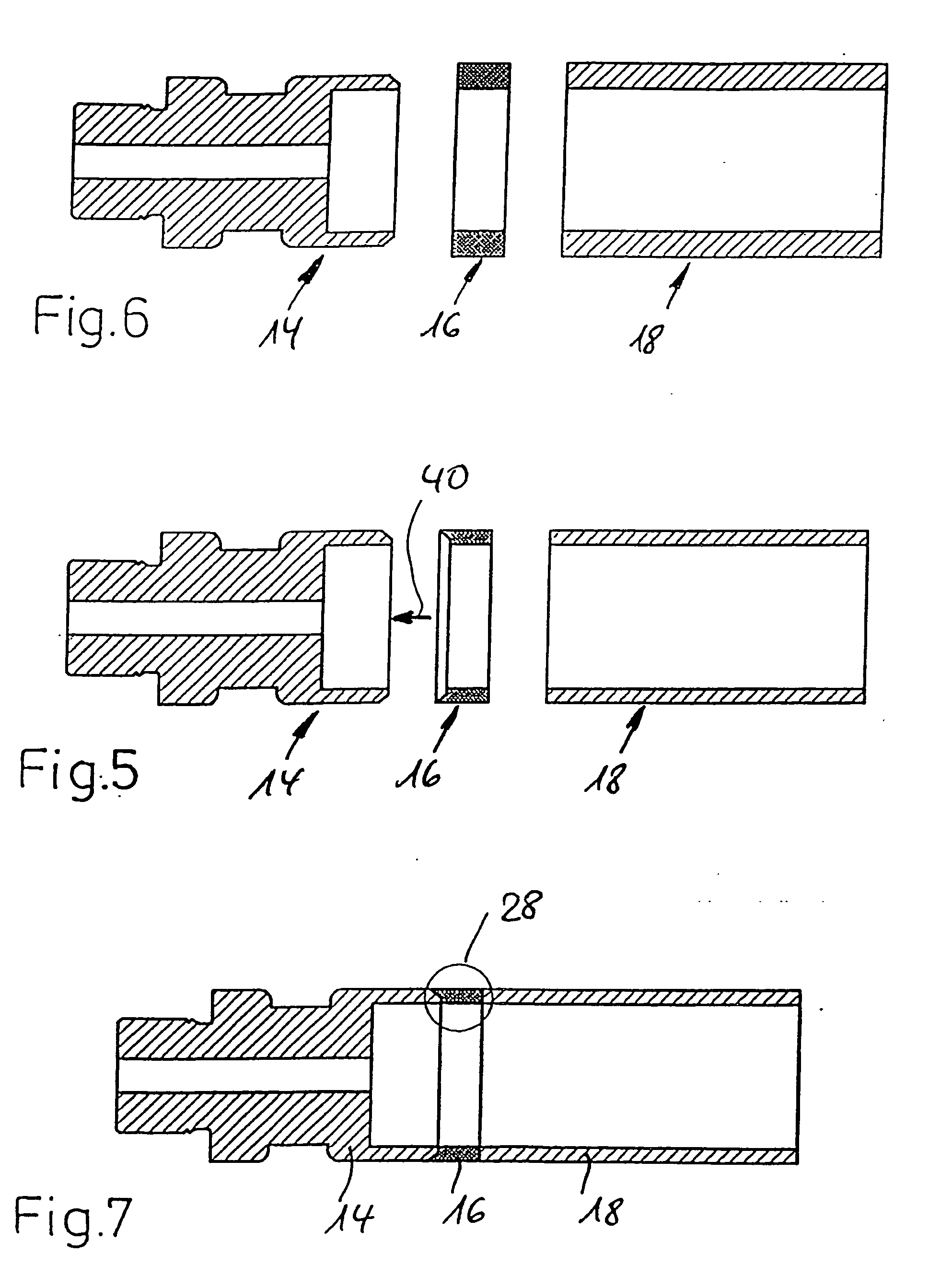
[0032] Specifically, in the example of embodiment shown, the core 14 was rotated at ...


PUM

PropertyMeasurementUnit
Pressureaaaaaaaaaa
Pressureaaaaaaaaaa
Pressureaaaaaaaaaa

Abstract

The invention relates to an electromagnetic actuating device, comprising an armature (20) which is provided in a housing (10) in such a way that it can be moved in an axial direction relative to a magnet frame (12) consisting of a core section (14) and a yoke section (18), and a coil device (24) which can be subjected to an electrical current in order to generate the movement, wherein the magnet frame is designed in a hollow-cylindrical manner in such a way that it at least partially surrounds the armature and comprises an intermediate section (16) consisting of non-magnetic material between the core section and the yoke section, wherein a permanent material connection is established in at least one of the cross-over areas (28) between the yoke section and the intermediate section and between the intermediate section and the core section by means of a friction welding method.

Description

BACKGROUND OF THE INVENTION [0001] The present invention relates to an electromagnetic actuating device including a hollow, cylindrical magnet that has a core section and a yoke section separated by an intermediate section of non-magnetic material. [0002] Such a device as an electromagnetic actuator, for example for use in connection with the control of valves for hydraulic or pneumatic systems or switching applications, is known in a general manner from the prior art. An armature made of magnetic material is movably guided in a magnet frame in order to carry out the essentially linear actuating movement; the magnet frame is surrounded by a coil and is held in a suitably designed housing. By subjecting the coil to electrical current, the armature is then set in the desired motion in order to carry out the actuating movement. [0003] In such electromagnetic actuators, the magnet frame, which is typically elongate, includes a core section and a yoke section. To properly guide or shape ...

Claims


Application Information

Patent Timeline
IPC IPC(8): H01F7/08B23K20/12B60T8/36H01F7/16
CPCB23K20/12B23K20/129H01F7/1607H01F7/081B60T8/3615
Inventor BURGER, VOLKERLANGEBAHN, HANS-WILLIRIEDLE, ACHIM
Owner ETO MAGNETIC GMBH
Why Eureka
Try Eureka