Method and apparatus for determining surface displacement based on an image of a retroreflector attached to the surface

a retroreflector and surface technology, applied in the field of surface displacement determination, can solve the problems of distorting measurements, challenging the daytime detection of light emitted by led or lasers and reflected off objects,

Inactive Publication Date: 2006-02-09
AVAGO TECH INT SALES PTE LTD
View PDF8 Cites 38 Cited by
  • Summary
  • Abstract
  • Description
  • Claims
  • Application Information

AI Technical Summary

Benefits of technology

[0009] The displacement of the surface may be used to determine a variety of different types of useful information, including, for example, the value of some physiol

Problems solved by technology

When a light emitting diode (LED) or laser is used by the imaging system to illuminate the object of interest, the simultaneous presence of broad-spectrum solar radiation can make detecting light emitted from an LED or laser and reflected off an object quite challenging during the day.
Othe

Method used


Image

  • Method and apparatus for determining surface displacement based on an image of a retroreflector attached to the surface
  • Method and apparatus for determining surface displacement based on an image of a retroreflector attached to the surface
  • Method and apparatus for determining surface displacement based on an image of a retroreflector attached to the surface

Examples


Embodiment Construction

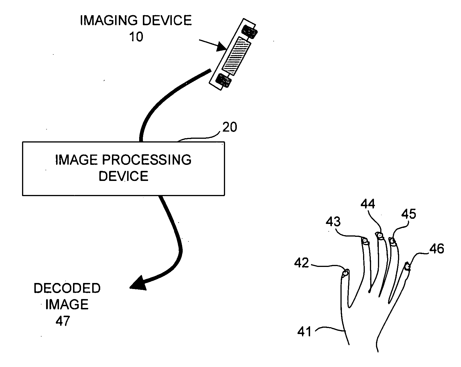
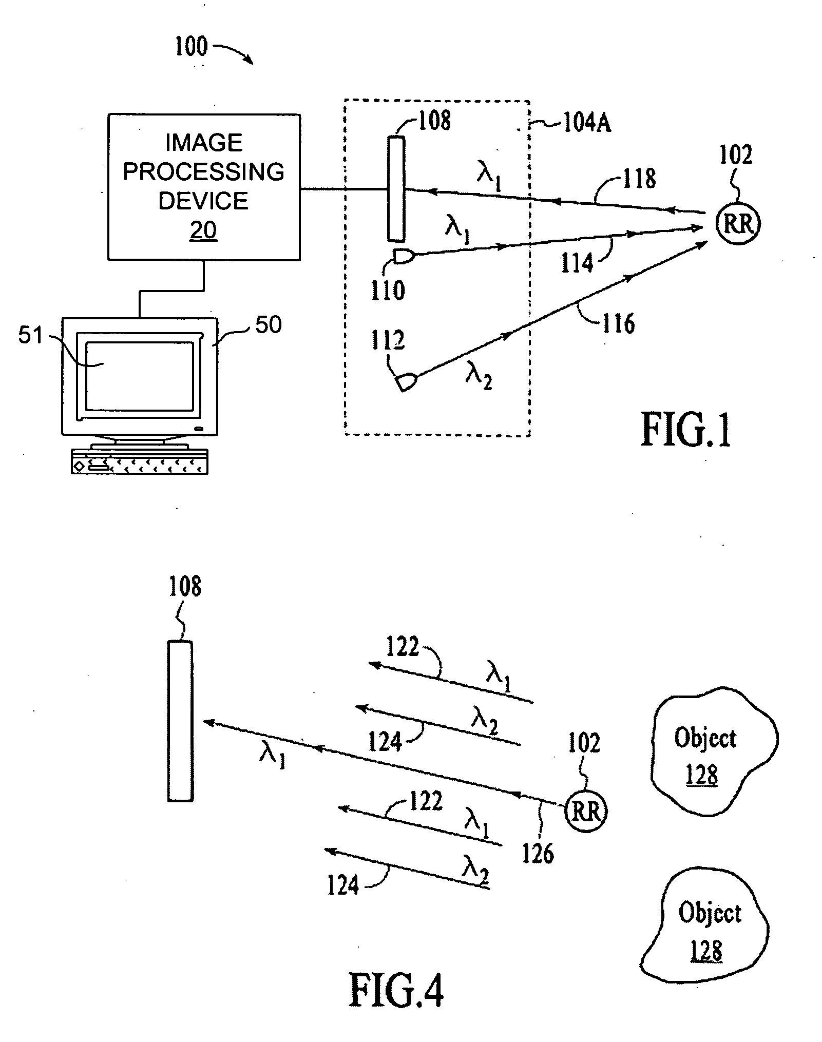
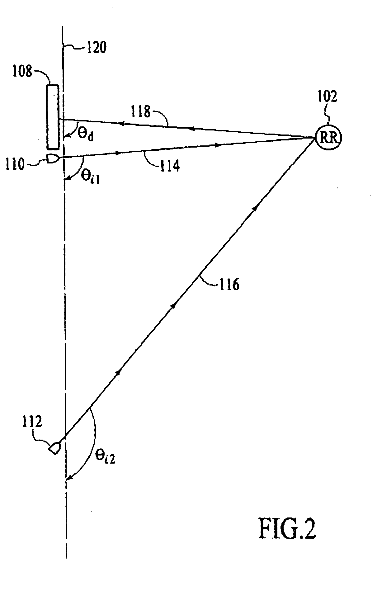
[0021] In accordance with the invention an imaging technique is provided that uses imaging information relating to a retroreflector attached to a surface of an object of interest to determine the shape and / or displacement of the surface of the object. A variety of types of information may then be ascertained based on the determination as to the shape and / or displacement of the surface of the object. Examples of a few different imaging systems that are suitable for this purpose are described below with reference to FIGS. 1-6B. Prior to describing these exemplary imaging systems, the manner in which the shape and / or displacement of a surface of an object may be ascertained from image information acquired relating to a retroreflector attached to the surface will be described with reference to FIGS. 7A-10.

[0022]FIGS. 7A and 7B illustrate an object of interest 2 that is being monitored by an imaging device 1 for changes in pressure. FIG. 7A represents the situation in which the object 2...


PUM


Abstract

An imaging system and method are provided that use imaging information relating to positions of one or more retroreflectors attached to one or more surfaces of an object of interest to determine the shape and/or displacement of the surface or surfaces on which the retroreflector or retroreflectors are located. A variety of types of information may then be ascertained based on the determination as to the shape and/or displacement of the surface of the object, such as the value of some physiological parameter of a patient, internal and external pressure of an object, acoustical vibrations sensed by a microphone, positions of fingertips on a keyboard, etc.

Description

CROSS-REFERENCE TO RELATED APPLICATIONS [0001] This application is a continuation-in-part and claims the benefit of the filing date of U.S. patent application to Fouquet et al. entitled “Method and system for wavelength-dependent imaging and detection using a hybrid filter”, having application Ser. No. 10 / 739,831, filed on Dec. 18, 2003 and published on Jun. 23, 2005, and which is incorporated by reference herein in its entirety.BACKGROUND OF THE INVENTION [0002] A wide variety of systems exist for detecting and / or imaging an object of interest. Detecting an object of interest generally involves determining the absence or presence of the object, while imaging involves obtaining an electronic representation of the object based on light emanating or being reflected from the object. Additionally, often times there is value in monitoring the displacement of part of the surface of the object. [0003] Wavelength-dependent imaging is one technique for imaging or detecting an object, and typ...

Claims


Application Information

Patent Timeline
IPC IPC(8): G01B11/14G01J3/10G01J3/12G01J3/26G01J3/28G01J3/427
CPCG01J3/10G01J3/26G01J3/2823G01J2003/1213G01J3/501G01J3/51G01J3/427G01J3/00
Inventor VENKATESH, SHALINIHAVEN, RICHARD EARLWENSTRAND, JOHN S.
Owner AVAGO TECH INT SALES PTE LTD
Why Eureka
Try Eureka