Network facsimile apparatus
a facsimile and network technology, applied in the direction of electrical equipment, pictoral communication, etc., can solve the problems of difficult negotiation and determination of optimal communication speed
- Summary
- Abstract
- Description
- Claims
- Application Information
AI Technical Summary
Problems solved by technology
Method used
Image
Examples
first embodiment
[0019]FIG. 3 is a flowchart of operations performed by the sender terminal 1 and the receiver terminal 2 according to the present invention.
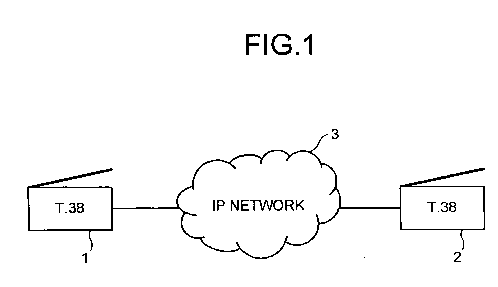
[0020] The sender terminal 1 determines whether a destination terminal (the receiver terminal 2) is a direct-connection type IAF T.38 terminal (step S1, hereinafter omitting “step”). If the destination terminal is a direct-connection type IAF T.38 terminal, the sender terminal 1 negotiates with the receiver terminal 2 to determine a T.38 communication control protocol. If the protocol is determined to be a transmission control protocol (TCP) (Yes at S2), the sender terminal 1 sends a T.38 packet at a highest possible transmission speed without controlling the transmission speed (S3). If it is determined that the destination terminal is not a direct-connection type IAF T.38 terminal at S1, or if the protocol determined at S2 is not TCP (e.g. user datagram protocol (UDP)), the sender terminal 1 controls the transmission speed when sending the T.38...
second embodiment
[0024]FIG. 4 is a flowchart of operations performed by the sender terminal 1 according to the present invention.
[0025] First, the sender terminal 1 makes a call connection to the receiver terminal 2 (S21). The sender terminal 1 determines whether a call connection message received from the receiver terminal 2 includes identification (ID) data of the receiver terminal 2 (S22). If ID data is included, the sender terminal 1 determines whether the ID data is that of a registered T.38 terminal (S23). If the ID data is registered, the sender terminal 1 sends a T.38 packet at a highest possible transmission speed without controlling the transmission speed, similarly to S3 in FIG. 3 (S24). Moreover, if registered ID data is not found at S22 or S23, the sender terminal 1 controls the speed when sending the T.38 packet to the receiver terminal 2. In this case, T.38 packet is sent at a speed as low as that of a G3 facsimile apparatus (S25).
[0026] The sender terminal 1 determines a machine mod...
third embodiment
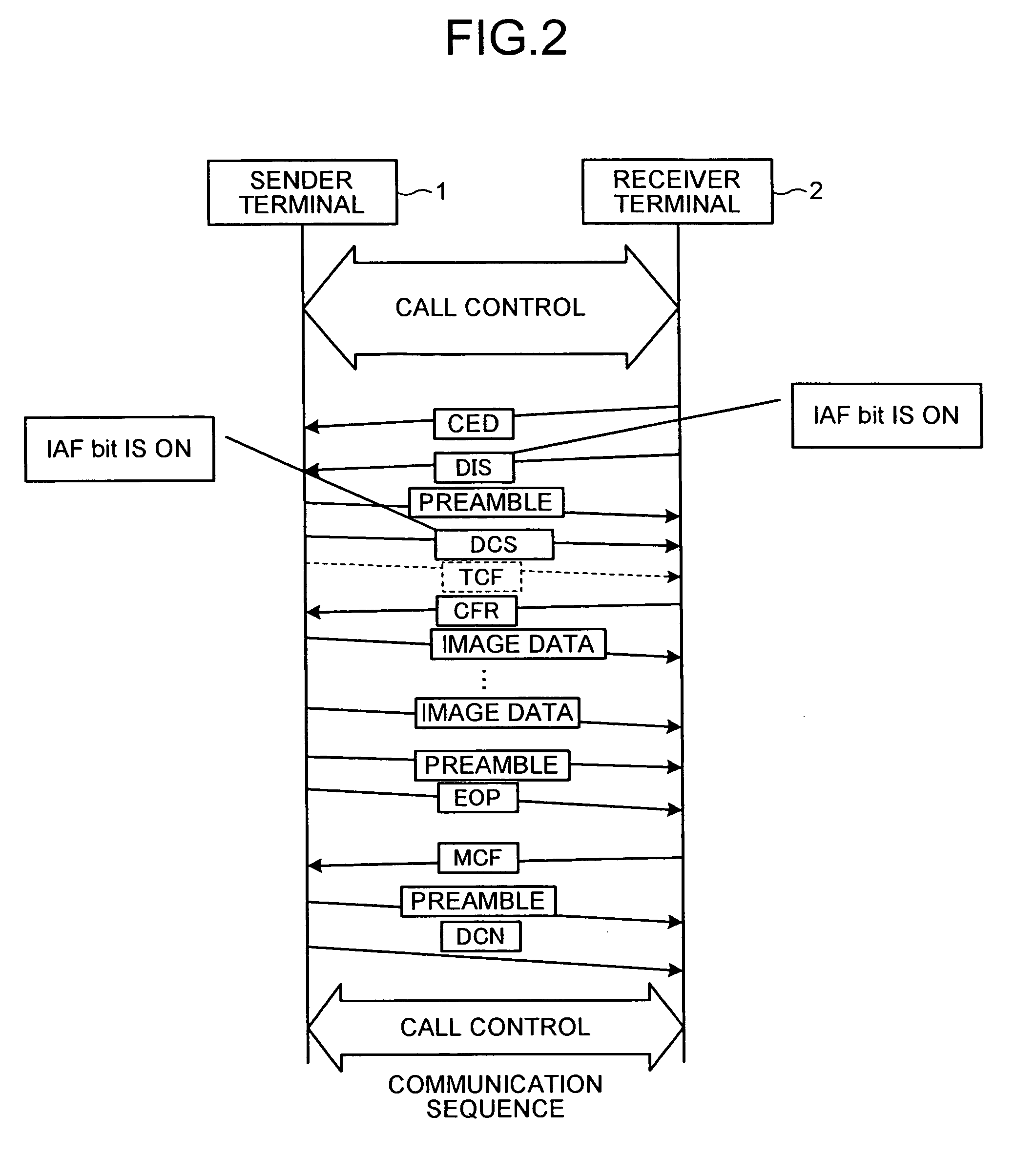
[0027]FIG. 5 is a flowchart of operations performed by the sender terminal 1 according to the present invention. The processings of S21 to S25 are the same as those of FIG. 4. When the sender terminal 1 is controlling the speed when sending the T.38 packet to the receiver terminal 2 at S25, and if the IAF bit turns “ON” for the signals of DIS and DCS (S26), the sender terminal 1 reduces the speed of the T.38 to that of a G3 facsimile apparatus at S27, similarly to S25.
[0028] According to the present invention, a direct-connection type IAF terminal can send data at a highest possible speed, by using a protocol such as TCP that has a flow control function. Thus, high-speed facsimile communication is performed at an optimal speed according to a processing capacity of a receiver terminal
PUM
 Abstract
Description
Claims
Application Information
 - R&D
- Intellectual Property
- Life Sciences
- Materials
- Tech Scout
- Unparalleled Data Quality
- Higher Quality Content
- 60% Fewer Hallucinations
Browse by: Latest US Patents, China's latest patents, Technical Efficacy Thesaurus, Application Domain, Technology Topic, Popular Technical Reports.
© 2025 PatSnap. All rights reserved.Legal|Privacy policy|Modern Slavery Act Transparency Statement|Sitemap|About US| Contact US: help@patsnap.com


