Fresnel zone plate based on elastic materials

a technology of elastic materials and zone plates, applied in the field of elastic fresnel zone plates, can solve the problems of low efficiency and easy production

Inactive Publication Date: 2006-02-09
PANASONIC CORP
View PDF4 Cites 38 Cited by
  • Summary
  • Abstract
  • Description
  • Claims
  • Application Information

AI Technical Summary

Benefits of technology

[0003] An exemplary embodiment of the present invention is a dynamically variable, amplitude grating based diffractive optic including: a substantially transmissive, elastic substrate; a substantially opaque, elastic material formed in a predetermined pattern on the first surface of the elastic substrate; and a substrate mount coupled to the elastic substrate to hold it under tension. The predetermined pattern of the substantially opaque, elastic material substrate forms an amplitude grating on the elastic substrate. The substrate mount includes a variable tensioner to stretch the elastic substrate and the substantially opaque, elastic material, thereby allowing at least one optical property of the amplitude grating to be dynamically varied.
[0004] Another exemplary embodiment of the present invention is a dynamically variable, amplitude grating based diffractive optic including: an elastic substrate; and a substrate mount coupled to the elastic substrate to hold the elastic substrate under tension. The elastic substrate includes at least one substantially transparent portion and at least one substantially opaque portion, the substantially opaque portion(s) arranged in a predetermined pattern to form an amplitude grating. The substrate mount includes a variable tensioner to stretch the elastic substrate, thereby allowing at least one optical property of the amplitude grating to be dynamically varied.

Problems solved by technology

Although diffractive lenses of this sort have relatively low efficiency and large chromatic aberrations, they are easy to produce and may be very compact, particularly when compared to refractive lenses.

Method used


Image

  • Fresnel zone plate based on elastic materials
  • Fresnel zone plate based on elastic materials
  • Fresnel zone plate based on elastic materials

Examples


Embodiment Construction

[0018] The present invention involves the use of amplitude gratings formed on elastic substrates to produce compact diffractive optics with variable optic characteristics, such as variable focal length diffractive lenses, variable grating period optical gratings, elliptical lenses with variable ellipticities, adaptive optics lenses, and variable amplitude masks that may be dynamically resized or distorted.

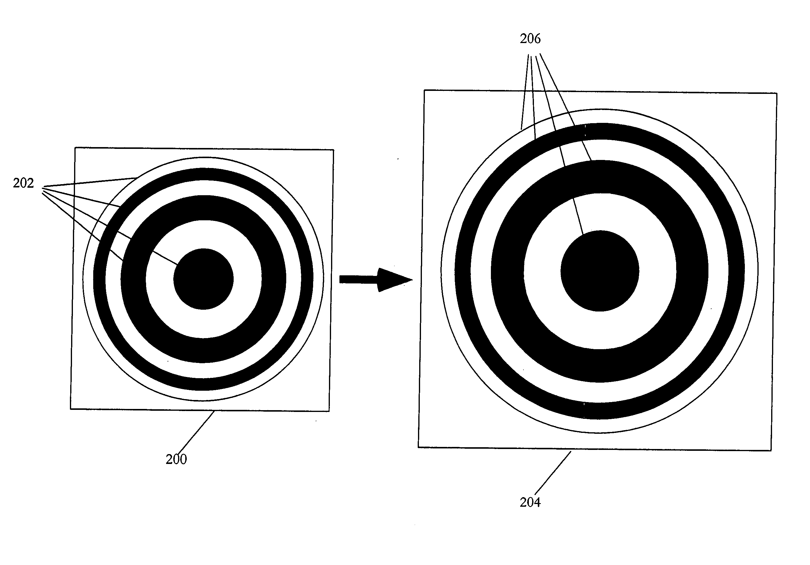
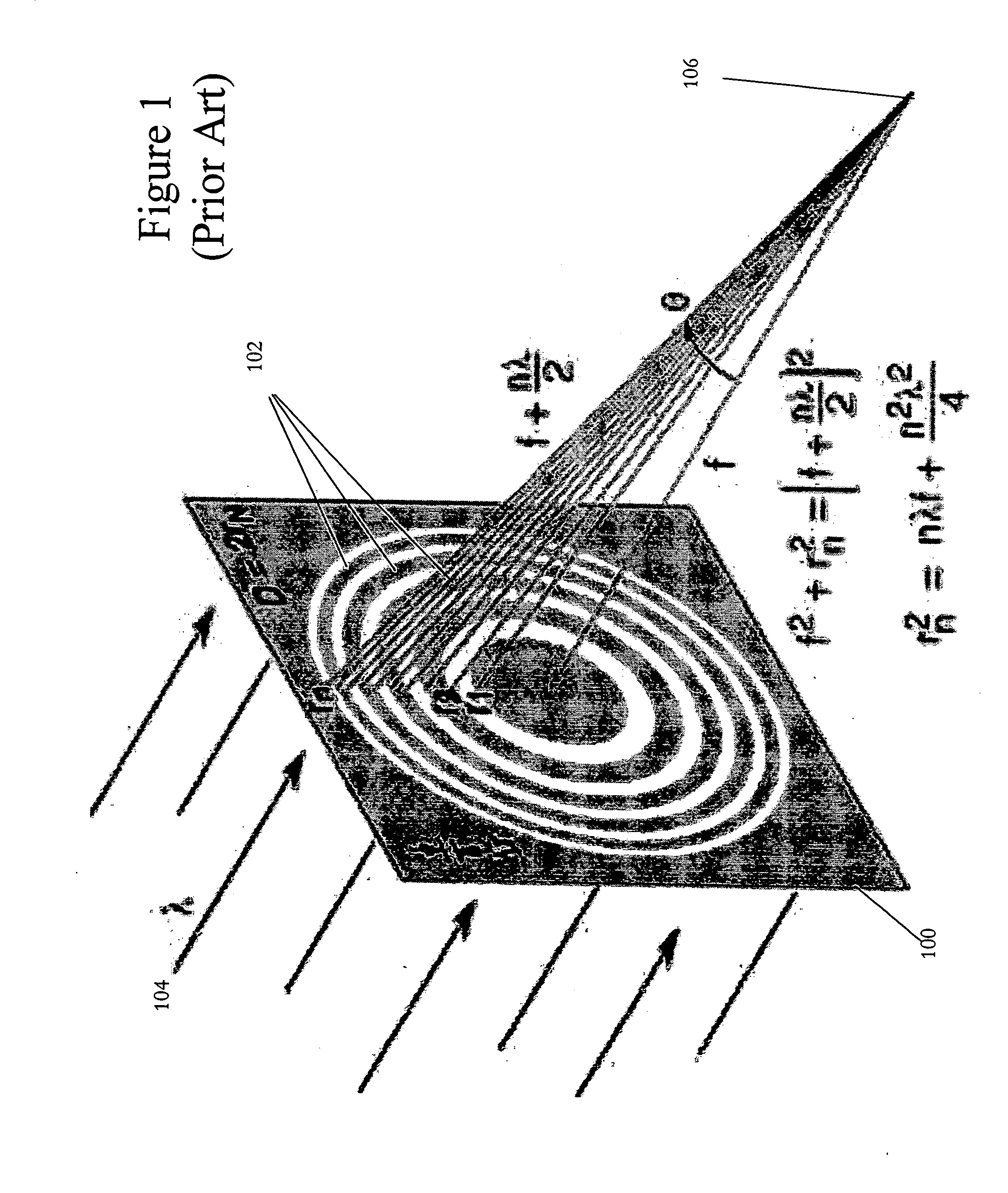
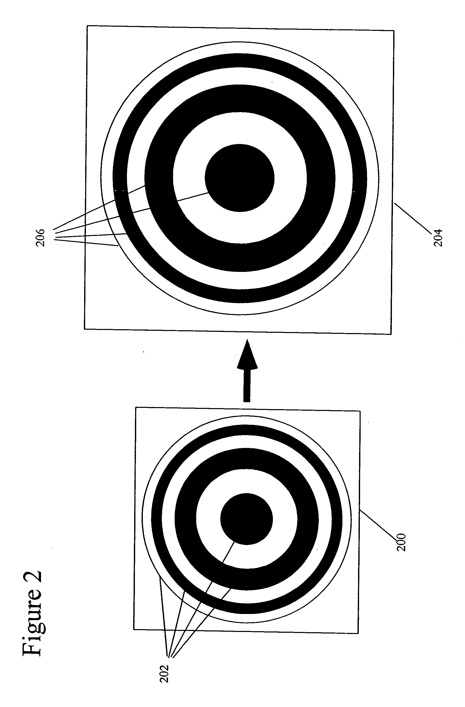
[0019] The first exemplary embodiment of the present invention is a variable focal length, and / or variable wavelength, two dimensional Fresnel zone plate as shown FIG. 2. Referring to the prior art two dimensional Fresnel zone plate shown in FIG. 1, the radii, rn, of the rings of amplitude grating 102 (or width the lines of the amplitude grating of a one dimensional Fresnel zone plate) used to focus a given wavelength, λ, at a given focal length, f, may be determined by Pythagorean theorem. The equations shown in FIG. 1 illustrate the derivation of Equation 1. rn2=n⁢ ⁢λ⁢ ⁢(f+n⁢ ⁢...


PUM


Abstract

A dynamically variable, amplitude grating based diffractive optic including: a substantially transmissive, elastic substrate; a substantially opaque, elastic material formed in a predetermined pattern on the first surface of the elastic substrate; and a substrate mount coupled to the elastic substrate to hold it under tension. The predetermined pattern of the substantially opaque, elastic material substrate forms an amplitude grating on the elastic substrate. The substrate mount includes a variable tensioner to stretch the elastic substrate and the substantially opaque, elastic material, thereby allowing at least one optical property of the amplitude grating to be dynamically varied. Alternatively, the elastic substrate may include at least one substantially transparent portion and at least one substantially opaque portion, the substantially opaque portion(s) arranged in a predetermined pattern to form the amplitude grating within the elastic substrate rather than on its surface.

Description

FIELD OF THE INVENTION [0001] The present invention concerns an elastic Fresnel zone plate. This elastic Fresnel zone plate may also allow for thin, dynamically adjustable optics. BACKGROUND OF THE INVENTION [0002] As products that include optical components become smaller and smaller, there is increased demand for smaller optical devices such as diffractive optics. One of the simplest forms of diffractive optics is amplitude gratings, which are simply based on the application of Huygens's principle to a light beam. FIG. 1 illustrates a two dimensional Fresnel zone plate based on amplitude grating 102, which is formed on substrate 100. Substrate 100 is substantially transmissive to incident light 104, which is show in FIG. 1 as being monochromatic with a wavelength of λ, and the concentric annular regions of amplitude grating 102 are substantially opaque to incident light 104. The concentric annular regions, or rings, of amplitude grating 102 are sized and arranged in a predetermine...

Claims


Application Information

Patent Timeline
Patent Type & Authority Applications(United States)
IPC IPC(8): G02B5/18
CPCG02B26/0808G02B27/4233G02B27/4205
Inventor LI, MING
Owner PANASONIC CORP
Why Eureka
Try Eureka