System and method for providing a time varying gain TDR to display abnormalities of a communication cable or the like

a technology of communication cable and gain tdr, which is applied in the field of system and method for providing a time varying gain tdr to display abnormalities in communication and telephone cable, can solve the problems of inability to implement equipment and the services to support that equipment, prohibitively expensive, and inability to work for different types of dsl operation. the effect of eliminating the need for user intervention in manually selecting the gain

Inactive Publication Date: 2006-02-09
VIAVI SOLUTIONS INC
View PDF8 Cites 5 Cited by
  • Summary
  • Abstract
  • Description
  • Claims
  • Application Information

AI Technical Summary

Benefits of technology

[0018] Another object is to provide a simple method and apparatus for interpreting TDR traces which will then require less user training.
[0020] A further object is to easily determine cable type by how well the back-scatter is matched. Further, if a user enters the incorrect wire type, some back-scatter slope will be present, and thus can be corrected. Accordingly, mixed cable types can be identified and compensated for and the need for user intervention in selecting gain manually is eliminated.

Problems solved by technology

However, in many areas of the country, such equipment and the services to support that equipment are either impractical to implement, prohibitively costly, or simply not scheduled to occur in the foreseeable future.
Lines that work fine for standard telephone communication do not always work for different types of DSL operation.
As one can imagine, this entire process is time consuming, labor intensive and costly.
As these lines become longer the loss of the line is higher and it becomes increasingly harder to detect these anomalies.
In most cases it takes considerable training and practice to discriminate between these various anomalies.
However since the size of this return trace is related to the cable type and distance, or in other words the cable loss (with the return trace decreasing in amplitude as the distance increases), there is no existing method used to definitely resolve these common cable plant problems.
Loss with cable plants of mixed cable types, makes detection for these faults even more complex.
Detecting multiple faults at different lengths cannot be done on the same trace, as the user must manually set the gain for only a particular range of interest.

Method used


Image

  • System and method for providing a time varying gain TDR to display abnormalities of a communication cable or the like
  • System and method for providing a time varying gain TDR to display abnormalities of a communication cable or the like
  • System and method for providing a time varying gain TDR to display abnormalities of a communication cable or the like

Examples


Embodiment Construction

[0051] The present invention is based on the development of a system for analyzing the structural and functional abnormalities of a copper pair line for xDSL service. By implementing the apparatus, methodology and protocol of the present invention, one can in a step-by-step process progressively test and trace the location and extent of the abnormalities without physically visiting the site.

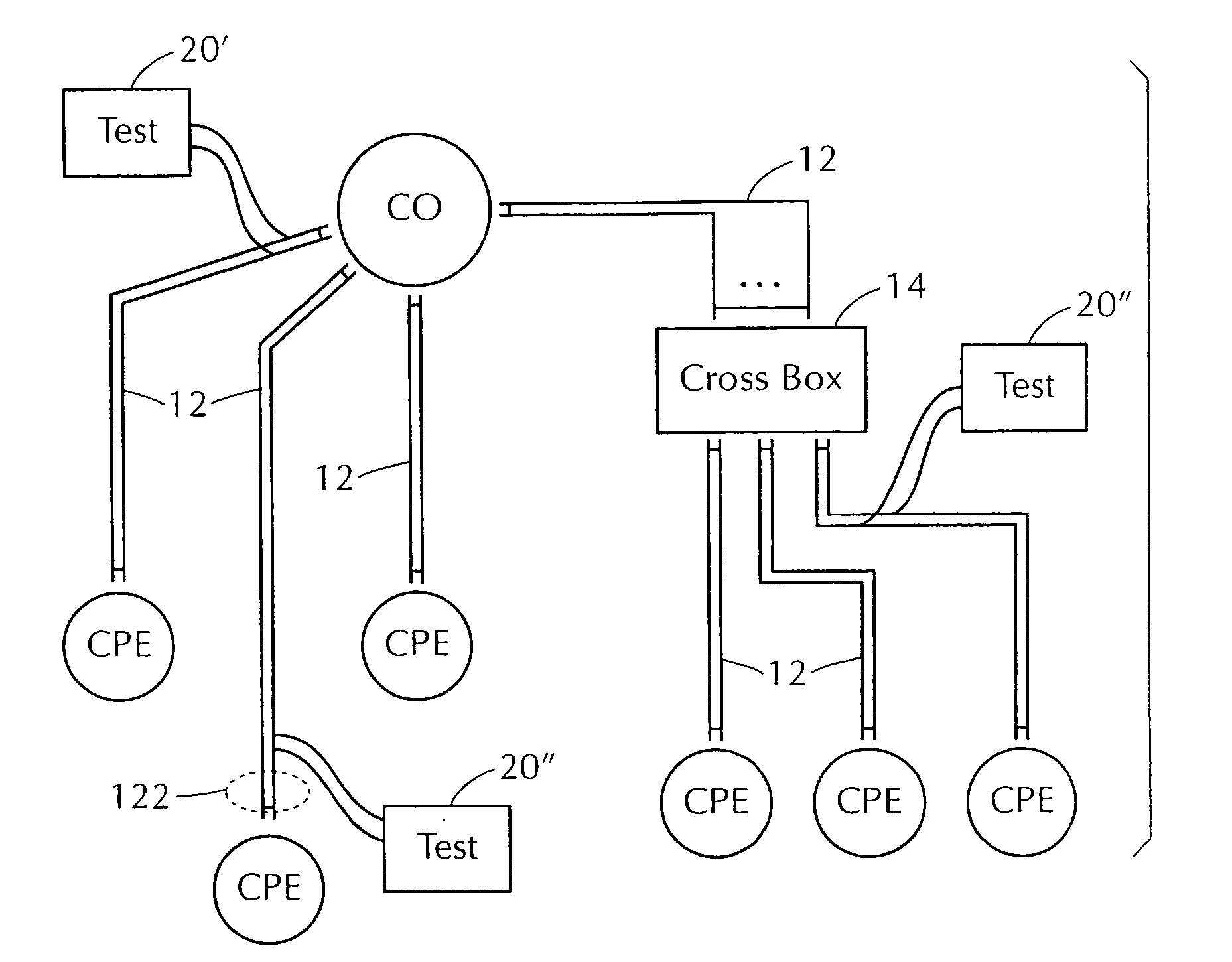
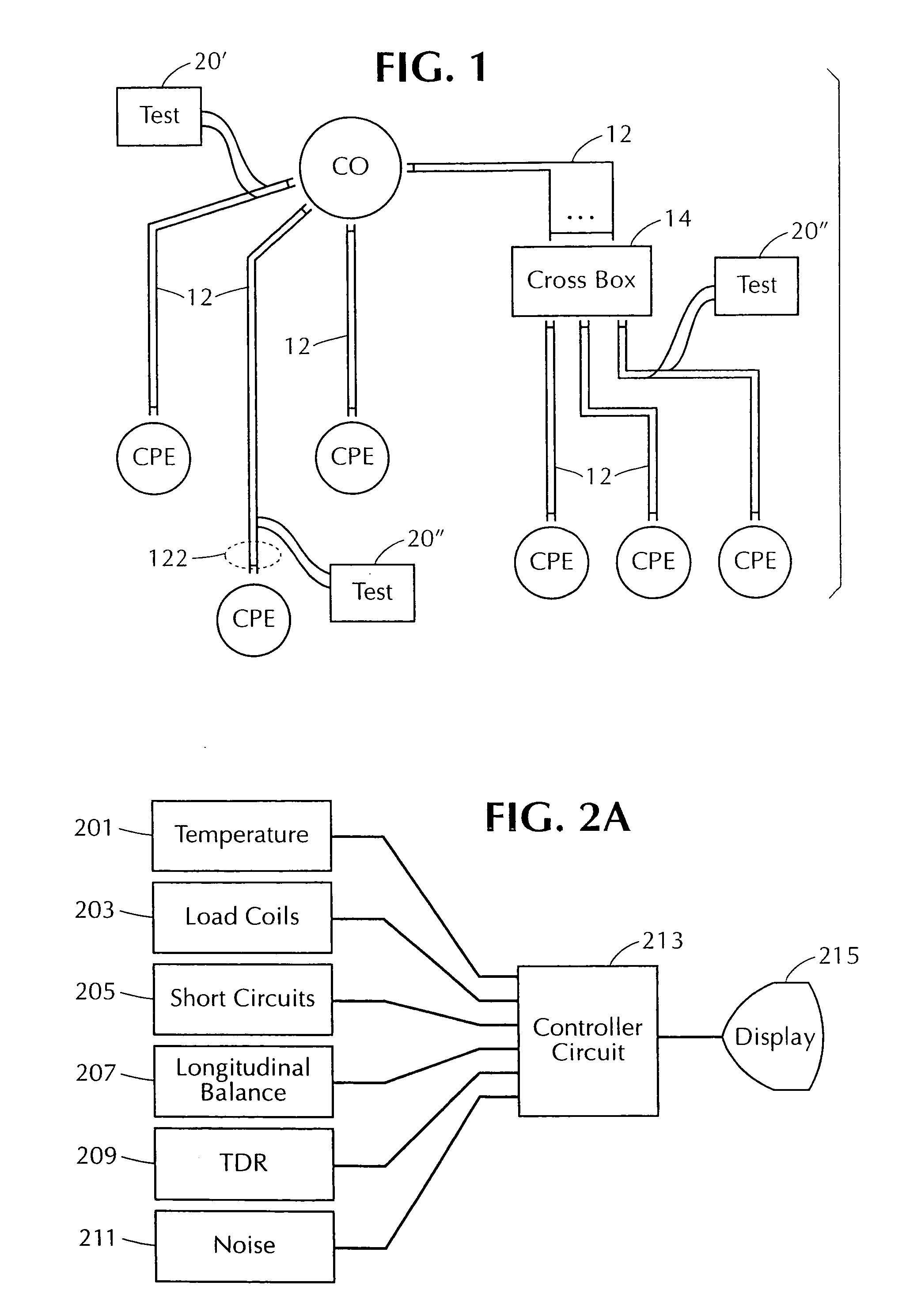
[0052]FIG. 1 illustrates a system block diagram of the testing environment of the present invention. In particular, a conventional telephone system that would be tested using the present invention would incorporate a central office or exchange CO through which a plurality of copper pair lines 12 are connected and processed. Each copper pair line would be composed of a cable loop pair 122 that has a CO end and a CPE end. Each cable loop pair terminates at a CPE end; a CPE is generally embodied in the copper pair lines that connect into individual homes or offices within proximity of the CO.

[0053...


PUM


Abstract

In a system and method for testing and displaying the abnormalities, includes opens, shorts, bridged-taps and wet sections, of a copper pair line for xDSL service use, the abnormalities are amplified and normalized so as to be displayed within a predetermined observation range. The normalization steps include piecewise gaining and biasing the reflected pulse of various gains to create a first normalized reflected trace which match the reflected traces within a predetermined observation range and thereby constitute a total smooth curve; and amplifying the first normalized reflected trace according to a function of time to create a second normalized reflected trace so as to eliminate an exponential gain decay curve of a no-fault copper pair line with the same predetermined characteristic parameters from the first normalized reflected trace to thereby obtain a second normalized reflected trace showing any amplified abnormalities.

Description

BACKGROUND OF THE INVENTION [0001] A. Field of the Invention [0002] The present invention related to a system and method for providing a time varying gain TDR to display abnormalities in a communication and telephone cable or the like by normalizing the levels of the reflected signals corresponding to a predetermined observation 10 range. The communication cable can be any copper pair line that can be used for IDSL, ADSL, HDSL, SDSL, SHDSL, and VDSL communication usage, as well as all other DSL-type technologies (hereinafter, “xDSL” indicating all the various DSL technologies and line codings). [0003] B. Description of the Prior Art [0004] Internet access providers, cable communication companies, etc. are constantly working to fill demands for real-time internet access through the installation of fiber-optic and other hi-speed communications lines. However, in many areas of the country, such equipment and the services to support that equipment are either impractical to implement, pr...

Claims


Application Information

Patent Timeline
Patent Type & Authority Applications(United States)
IPC IPC(8): G01V1/38H04L12/26
CPCG01R31/11H04Q2213/1316H04L43/50H04L12/2697
Inventor WYAR, PAUL
Owner VIAVI SOLUTIONS INC
Why Eureka
Try Eureka