Service and information management system for a telecommunications network

a technology of information management system and telecommunications network, applied in the direction of electrical equipment, interconnection arrangements, supervisory/monitoring/testing arrangements, etc., can solve the problems of data collection methods, call torn down, data collection methods not providing information regarding calls which failed in the call set-up stage,

Inactive Publication Date: 2006-02-09
AMERICAN TELEPHONE & TELEGRAPH CO
View PDF27 Cites 17 Cited by
  • Summary
  • Abstract
  • Description
  • Claims
  • Application Information

AI Technical Summary

Benefits of technology

[0032] In preferred embodiments, the instructions residing on the processor allow the apparatus to centrally perform various functions associated with the telecommunications network, including call processing and routing, automatic fault detection and correction, providing services to customers in an interactive manner, fraud detection and control, identification of patterns of abuse of the network and producing a record of each call placed within the network.

Problems solved by technology

If the dialed number does not match an entry in the global title translation table, either the table is in error or the local exchange carrier switch or competitive access provider's switch misrouted the call.
The local exchange carrier responds with a release complete message, resulting in the call being torn down.
The terminating switch node in response sends a Q.931 protocol release complete message to the private branch exchange, which also results in the call being torn down.
Typically, there is no provision for clock synchronization throughout the network, so that if the local clock is not accurate, calls of customers subscribing to a time-of-day routing service may be directed to the wrong location.
These data collection methods, however, do not provide information regarding calls which failed in the call set-up stage, such as calls which never reached a service control point.
In addition, part of the processing power of the service control point is expended to perform these functions when the service control point collects and sends data to a central computer, and placing equipment to collect data on each link to each service control point represents a cumbersome and costly method of data collection.
Currently, measurement of post-dialing delay is limited because there is no satisfactory mechanism in place to monitor post-dialing delay on an ongoing basis.
Utilizing the originating switch node to perform these functions results in limited flexibility for user-defined billing, and the inability to detect and control fraud or abuse of the telecommunications network, such as stalking, in real-time.
Also, since data regarding calls is collected from originating switch nodes and other network elements only periodically, real-time detection of faults in the network is not possible.
Fault management has been handled in various ways in prior art systems, none of which are completely satisfactory.
This can result in errors occurring and remaining undetected for a certain period of time.
Even using the call surveillance technique, inability to effectively and efficiently monitor the status of each call entering a telecommunications system in real-time may result in errors occurring and going undetected.

Method used


Image

  • Service and information management system for a telecommunications network
  • Service and information management system for a telecommunications network
  • Service and information management system for a telecommunications network

Examples


second embodiment

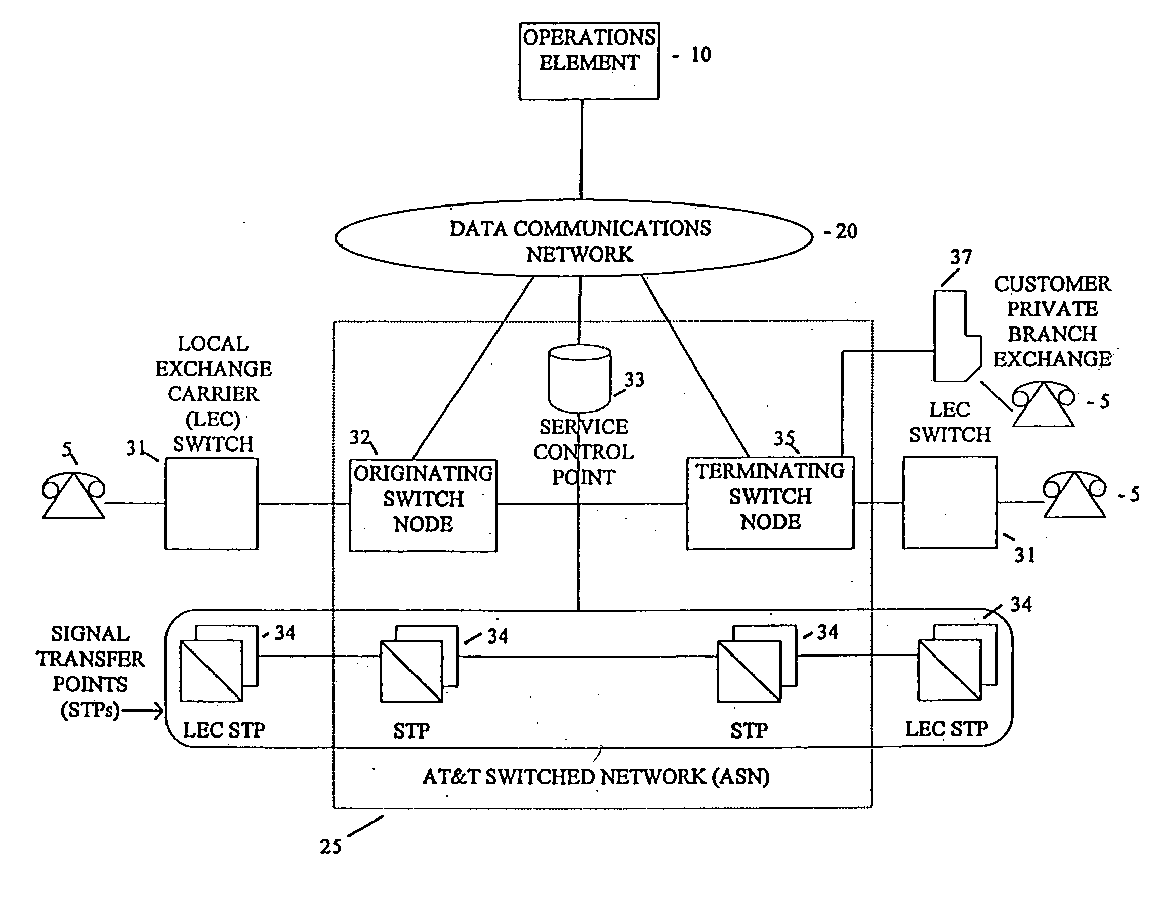
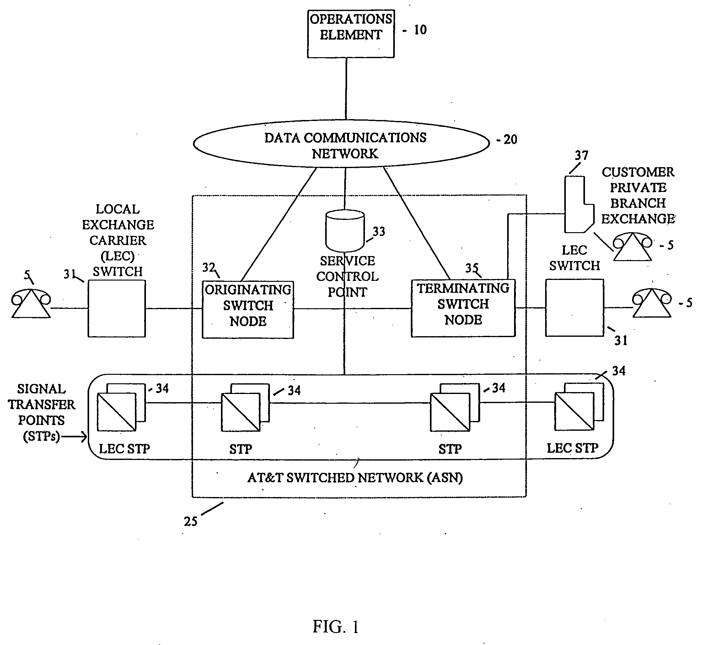
[0072] As illustrated in FIG. 7, the call routing function according to the present invention provides for an information packet 205 associated with a request message 61 to be received by the operations element 10 from a signal transfer point 34, rather than from an originating switch node 32. As in the preferred embodiment, the operations element 10 utilizes the call control database (shown in FIG. 5) to determine the processing and routing required for the call and forwards this information via a response message 62 to the originating switch node 32. The originating switch node 32, however, upon receiving the response message 62, must perform the additional function of correlating the response message 62 with the request message 61 it received from the signal transfer point 34. This correlation may be based on the identity of the local exchange carrier switch 31, the identity of the originating switch node 32, and other information contained in the request message. The originating...

third embodiment

[0074] the call routing function according to the present invention is illustrated in FIG. 8. A signal transfer point 34 detects a request message 61 associated with an incoming call. The signal transfer point 34 appends transaction information to the request message 61, forming an information packet 205, and sends the information packet 205 to a stand-alone operations element 10. The operations element 10 utilizes a call control database 11 which is connected directly to the operations element 10 to determine the processing and routing required for the call. The operations element 10 sends a response message 62 containing routing and processing instructions to an originating switch node 32 or, if the instructions reside on a service control point as discussed in connection with FIG. 6, instructs it to seek instructions from service control point 33 identified in the response message 62. The originating switch node 32 correlates the response message with the request message 61 it re...


PUM


Abstract

A system for service control and operations for a telecommunications network. In particular, an architecture and method for a service control and operations element system. The system communicates with a plurality of interconnected telecommunications network elements via a switching and signaling subsystem. The system provides and controls the various functions of the telecommunications network, such as call processing and routing, automatic fault detection and correction, providing services to customers in an interactive manner, fraud detection and control, identification of patterns of abuse of the network, collecting data regarding call activity at each network element, and producing a record of each call placed within the network.

Description

[0001] This is a application is a continuation of application Ser. No. 09 / 976,309, filed Aug. 15, 2001, allowed Jun. 20. 2005, which is a continuation of Ser. No. 09 / 041,439, filed Mar. 12, 1998, now U.S. Pat. No. 6,430,286, issued Aug. 6, 2002, which is a divisional of Ser. No. 08 / 837,830, filed Apr. 22, 1997, now U.S. Pat. No. 5,878,113, issued Mar. 2, 1999, assigned to the same assignee as the present invention, which is hereby incorporated by reference herein in its entirety.TECHNICAL FIELD [0002] The invention relates generally to service and operations control for telecommunications network, and more particularly to a service control and operations element system which performs and controls various functions of the telecommunications network. BACKGROUND OF THE INVENTION [0003] Management of modem telecommunications networks requires performing multiple functions, including call establishment and routing, fault management, call details recording used to compile customer bills, ...

Claims


Application Information

Patent Timeline
Patent Type & Authority Applications(United States)
IPC IPC(8): H04M7/00H04M3/22H04M3/36H04Q3/00
CPCH04M3/2254H04M3/2263H04M3/36H04Q3/66H04M2207/12H04Q3/0029H04M7/0093
Inventor BHUSRI, GURCHARAN S.
Owner AMERICAN TELEPHONE & TELEGRAPH CO
Why Eureka
Try Eureka