
Process of and apparatus for making a shingle, and shingle made thereby

a technology of shingle and apparatus, which is applied in the field of making roofing shingles and tiles, can solve the problems of reduced mechanical properties of the ultimate product, difficult processing of formulations into shingles and tiles, and color variations that are possible, so as to reduce the time required for molding operation

Inactive Publication Date: 2006-02-09
CERTAINTEED CORP
View PDF32 Cites 74 Cited by
  • Summary
  • Abstract
  • Description
  • Claims
  • Application Information

AI Technical Summary

Benefits of technology

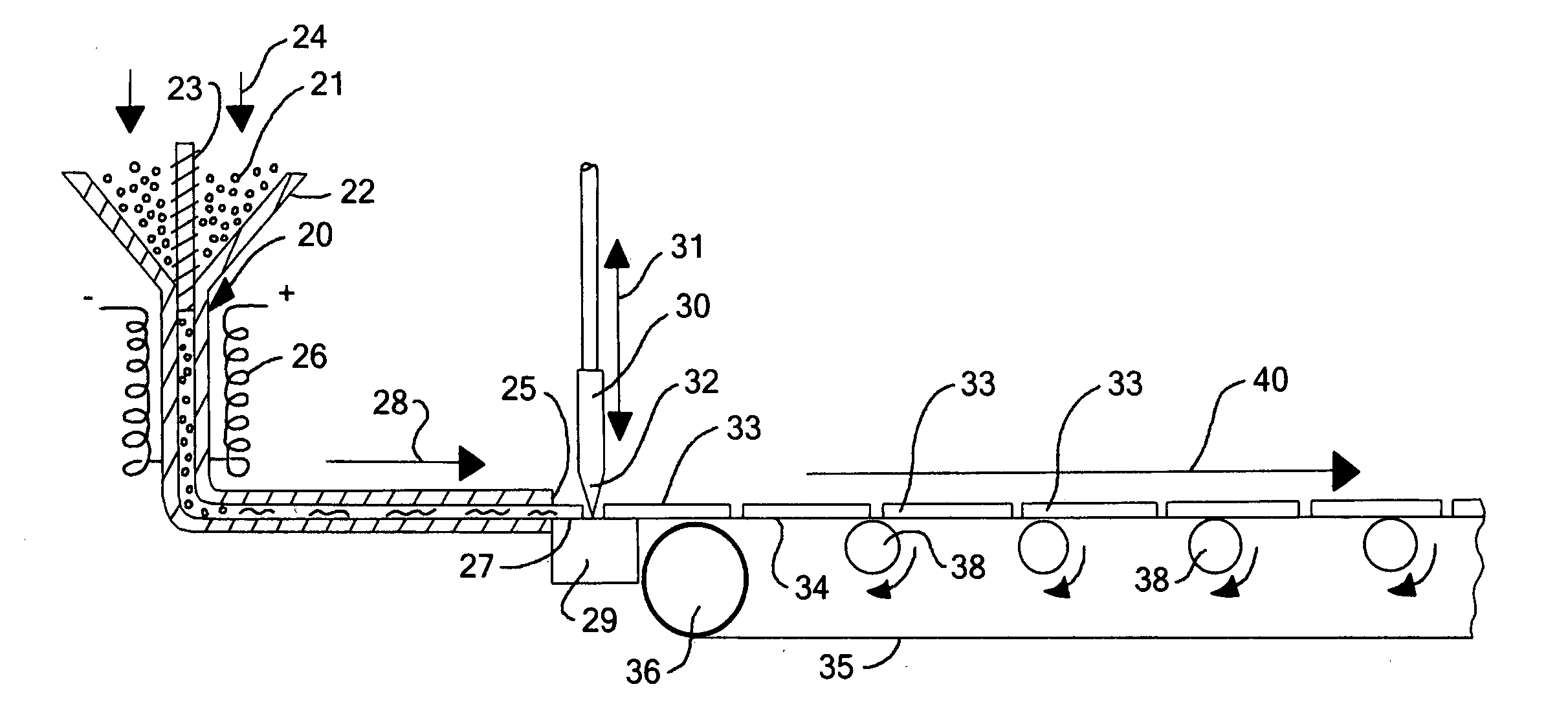
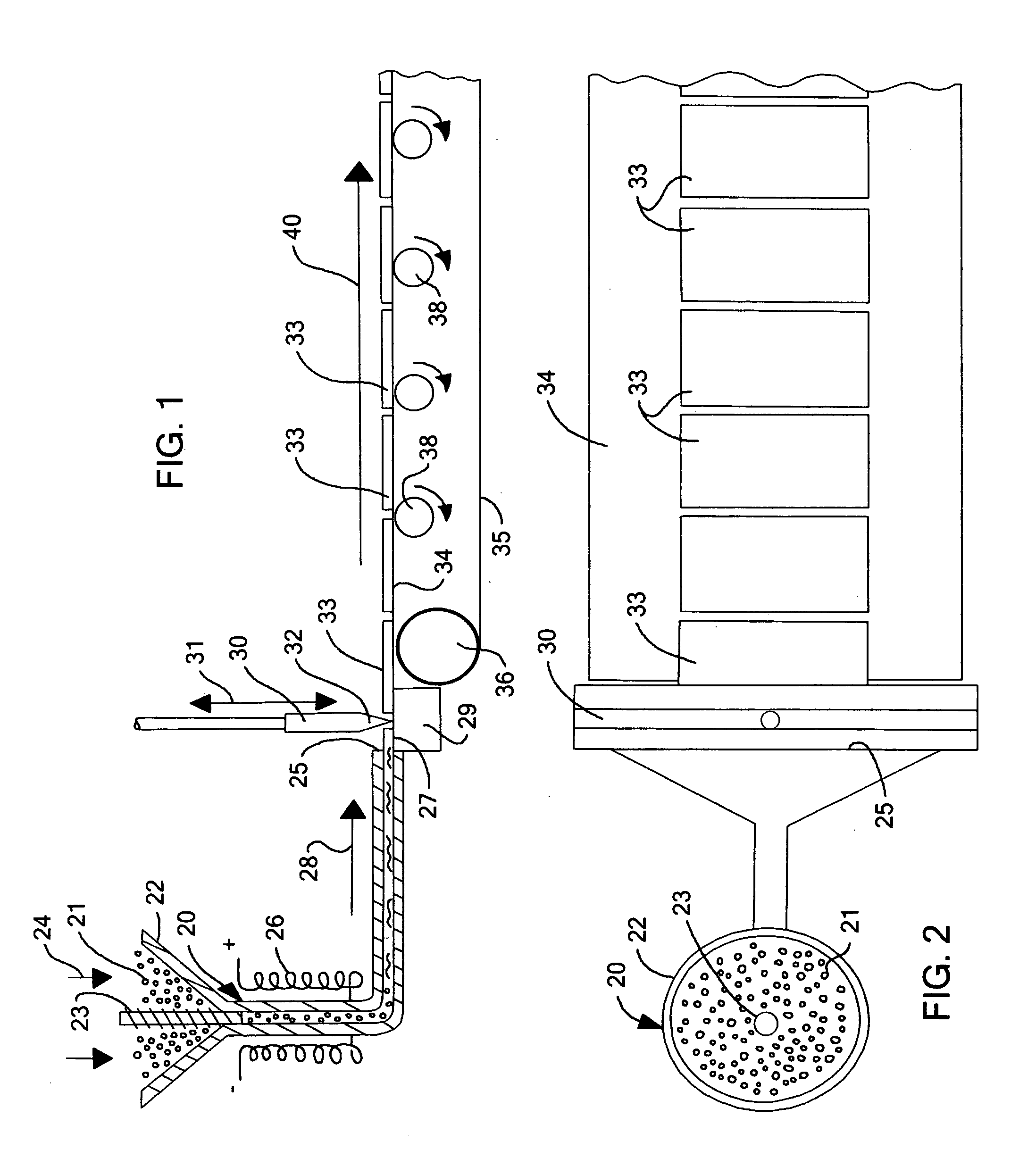
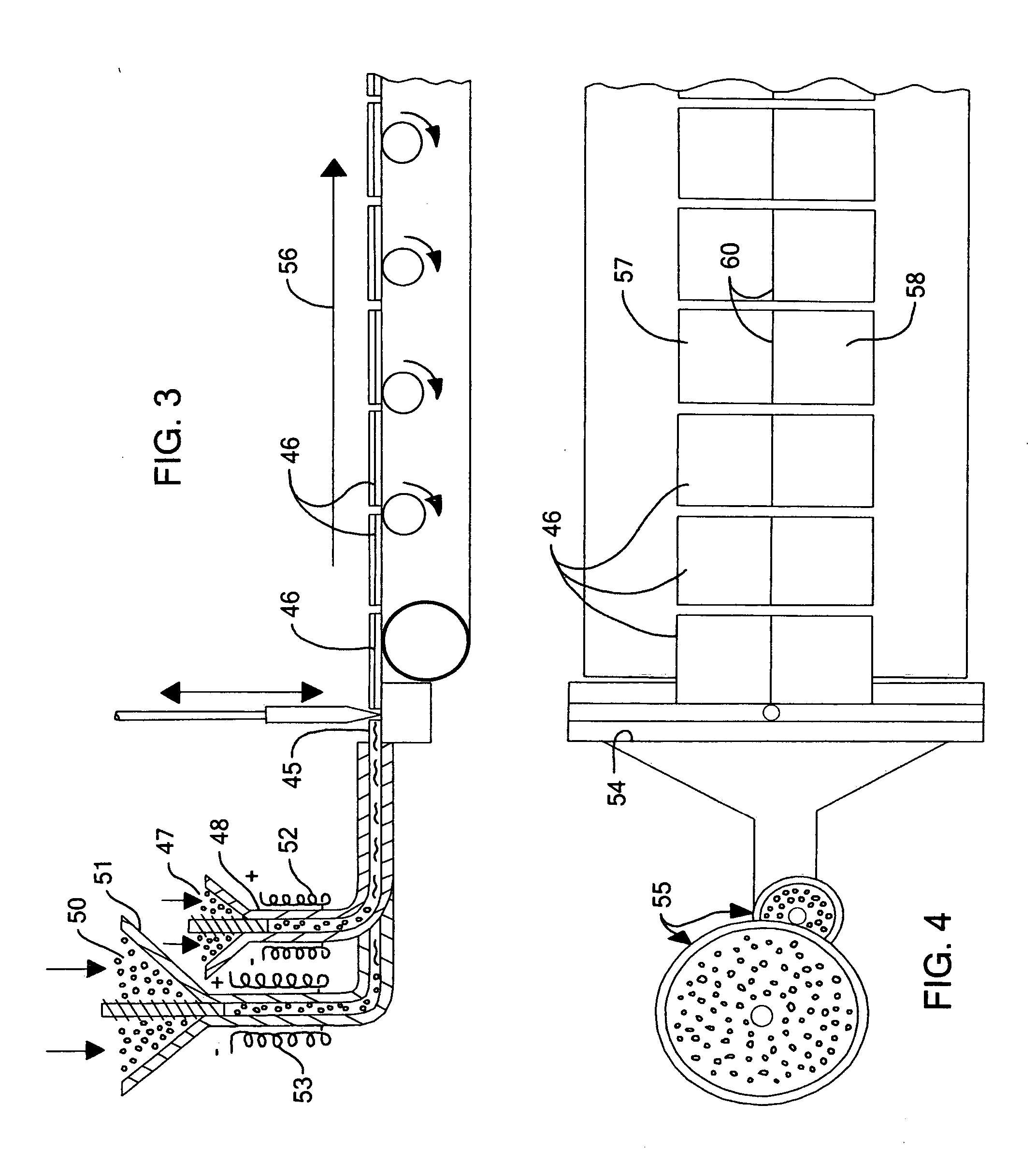
[0011] The present invention is directed to a process of making a shingle having a desired configuration, by a combination of extruding and molding, in order to reduce the time required for the molding operation. As used throughout the application, “shingle” should be considered to embrace “tile” also.

Problems solved by technology

The use of large quantities of such fillers reduces the mechanical properties of the ultimate product, however.
Additionally, the use of large quantities of fillers limits the color variations that are possible in the products and makes the processing of the formulations into shingles and tiles very difficult.
Typically, roofing shingles and tiles made of such material having waste for filler do not provide good weather resistance for the products.
Additionally, the warranty periods that can reasonably be provided for such products tend to be short in duration.
Furthermore, such building industry roofing products have relatively low impact strength, especially at low temperatures.
Insofar as their available colors are concerned, such tend to be limited to the colors gray and black.
Additionally, molding operations tend to be capital intensive, with relatively high manufacturing costs, although molding techniques do provide a high level of definition or dimension control.
Also, there is a disadvantage to molding techniques, in general, in that the length of the cycle for injecting material into the mold, molding to the desired shape, and ejecting the shape from the mold is largely a function of the time required to cool the molten thermoplastic material before it can be removed from the mold.
In order to achieve the necessary cooling, the time required causes a lengthening of the manufacturing cycle, which increases the capital costs of investment in molds and machinery for a required output, thereby substantially increasing manufacturing costs.

Method used


Image

  • Process of and apparatus for making a shingle, and shingle made thereby
  • Process of and apparatus for making a shingle, and shingle made thereby
  • Process of and apparatus for making a shingle, and shingle made thereby

Examples


example 1

[0088] Pellets of a flexibilized polypropylene copolymer, 18S2A, available from Huntsman Chemical, Salt Lake City, Utah, were combined in a Werner Pfleiderer twin screw extruder with calcium carbonate, Hubercarb Q3, available from J. M. Huber Corporation, Atlanta, Ga., and a stabilizer package, FS-811, available from Ciba Specialty Chemicals, Tarrytown, N.Y., using gravimetric feeders to obtain a mixture that was 49.25 wt % polypropylene, 50 wt % calcium carbonate and 0.75% stabilizer package. This mixture was extruded as a strand and chopped into pellets of filled polypropylene for later processing.

example 2

[0089] Pellets of Example 1 were dried and fed into a single screw extruder, MPM 3.5 inch in diameter, 24:1 L / D, equipped with a flex lip die and extruded to form a sheet. The die was adjusted to produce an extrudate that was about 19 inches in width and having a profile with varying thickness across the sheet ranging from about 0.375 inches to 0.245 inches. The sheet was extruded onto a first conveyor belt having variable speed matched to the extrudate speed. The temperature of the sheet was about 380 F when exiting the die.

[0090] When a section of sheet 13 inches in length had been extruded, the sheet was cut from the die lip. While still hot, the section of 19″×13″ sheet was carried to a second conveyor belt and transferred to and centered on the lower plate of a mold having a size of 18″×12″. Infrared lamps were provided above the conveyor to maintain the temperature of the sheet during transfer. On reaching the lower mold plate, the surface temperature was about 300 F. The upp...

example 3

[0092] Pellets of a flexibilized polypropylene copolymer, 18S2A, available from Huntsman Chemical, Salt Lake City, Utah, were combined in a Werner Pfleiderer twin screw extruder with calcium carbonate, Hubercarb Q3, available from J. M. Huber Corporation, Atlanta, Ga., using gravimetric feeders to obtain a mixture that was 50 wt % polypropylene and 50 wt % calcium carbonate. This mixture was extruded as a strand and chopped into pellets of filled polypropylene for later processing.


PUM

PropertyMeasurementUnit
Temperatureaaaaaaaaaa
Thicknessaaaaaaaaaa
Forceaaaaaaaaaa

Abstract

A process and apparatus for making a shingle, together with the shingle made thereby, is provided, in which one or more thermoplastic materials are extruded or co-extruded to form an extrudate, with the extrudate being cut into a preliminary shingle shape, which is allowed to dissipate heat, and then is delivered to a compression mold, wherein the preliminary shingle shape is compression molded to substantially its final dimensions and is then discharged from the mold and allowed to cool.

Description

CROSS-REFERENCE TO RELATED APPLICATIONS [0001] This application is a continuation-in-part of U.S. patent application Ser. No. 10 / 452,059, filed Jun. 2, 2003, the complete disclosure of which is herein incorporated by reference.BACKGROUND OF THE INVENTION [0002] In the art of making roofing shingles and tiles for exterior application in the building industry, various approaches have been made toward making shingles and tiles that are manufactured, but give the appearance of being made of traditional natural materials, such as wood cedar shakes, tiles, slate, etc. [0003] In many instances, such shingles and tiles are made of bitumen coated mat having granules on the exterior surface, with the granules being provided in various designs, shades, color configurations, etc., to yield various aesthetic effects. [0004] It is also known, in making roofing shingles and tiles, to mold them to the desired shape by various molding techniques. The materials that are used in such molding technique...

Claims


Application Information

Patent Timeline
IPC IPC(8): E04D1/00B32B27/12B32B27/20E04D1/20
CPCB32B27/12Y10T428/24355E04D1/20B32B27/20
Inventor MACKINNON, THOMAS KEVINDODD, ROBERT E.KIM, JOONG YOUNWYLIE, DOUGLAS H.
Owner CERTAINTEED CORP
Learn More