Modular belt shaped to fit the shape of a loin

a module belt and loin technology, applied in the field of module belts, can solve the problems of reducing the efficiency of cutting with the knife(ves), affecting the quality of meat, and the same piece of meat moving along the same path, so as to achieve the effect of easy replacement, simple and easy maintenance of the belt, and easy replacemen

Inactive Publication Date: 2006-02-09
G E LEBLANC
View PDF5 Cites 8 Cited by
  • Summary
  • Abstract
  • Description
  • Claims
  • Application Information

AI Technical Summary

Benefits of technology

[0018] Moreover, the maintenance of the belt is much simpler and easier, since use is made of one or several chains as moving means. The rotation of the chain(s) can therefore be carried out with conventional elements that are easy to obtain and easy to replace whenever needs be.
[0019] Last of all, due to the fact that the belt according to the invention is provided with one or more chain(s), it is not subject to risk of elongation due to heat, as is the case with the existing belts. Moreover, it is much more resistant that the existing belts that are subjected to risk of tearing.

Problems solved by technology

One of the problems associated with the American loin pullers is related to the fact that the piece of meat moving along the same is much bigger and heterogeneous than a loin separated from the adjacent flank, as is the case in the first kind of equipment.
However, when the loin is moved onto such a recessed conveyor, the remaining part of the piece of meat may have some to its surface in contact with one side of the frame of the equipment or onto a guide, which can cause a displacement of the loin due to a friction of it on the equipment or guide.
Depending on the temperature of the piece of meat, the kind of refrigeration, the genetics and the thickness of the backfat, the friction may cause a motion of the muscular and bone mass of the loin, which can result in a lower efficiency of the cut achieved with the knife(ves) as well as a poor performance of the equipment.
By way of example, the blade bone can be moved together with the loin or be pulled up by excessive tension toward the external part of the machine and be cut by the knife(ves), which is a cause of problem for further processing the flanks or bellies.

Method used


Image

  • Modular belt shaped to fit the shape of a loin
  • Modular belt shaped to fit the shape of a loin
  • Modular belt shaped to fit the shape of a loin

Examples


Embodiment Construction

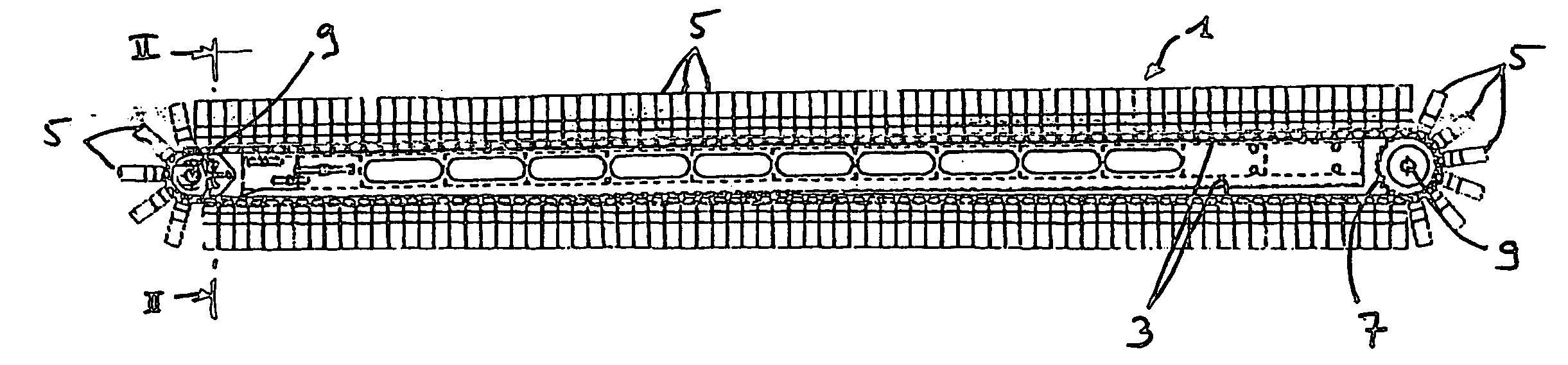
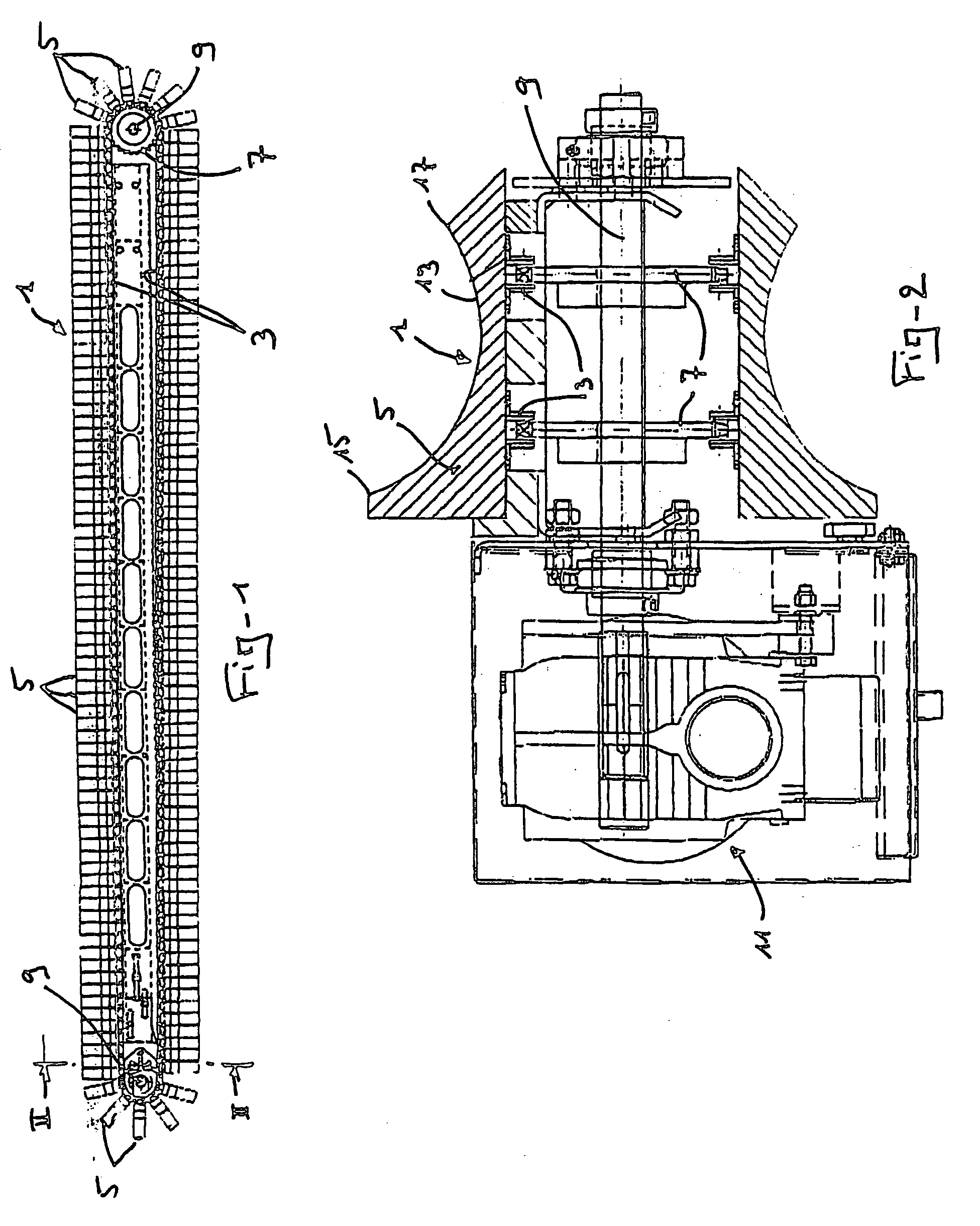
[0024] The modular belt 1 for a loin puller as shown in the accompanying drawings is specifically devised to be used in an American loin puller, that is a loin puller wherein the flank is not completely separated from the loin before the loin moves below a U-shaped knife whose purpose is to separate the back fat from the loin and separate the loin from the belly. An example of such an American loin puller is disclosed in U.S. Pat. No. 6,336,856 already mentioned, that was granted in the name of the Applicant.

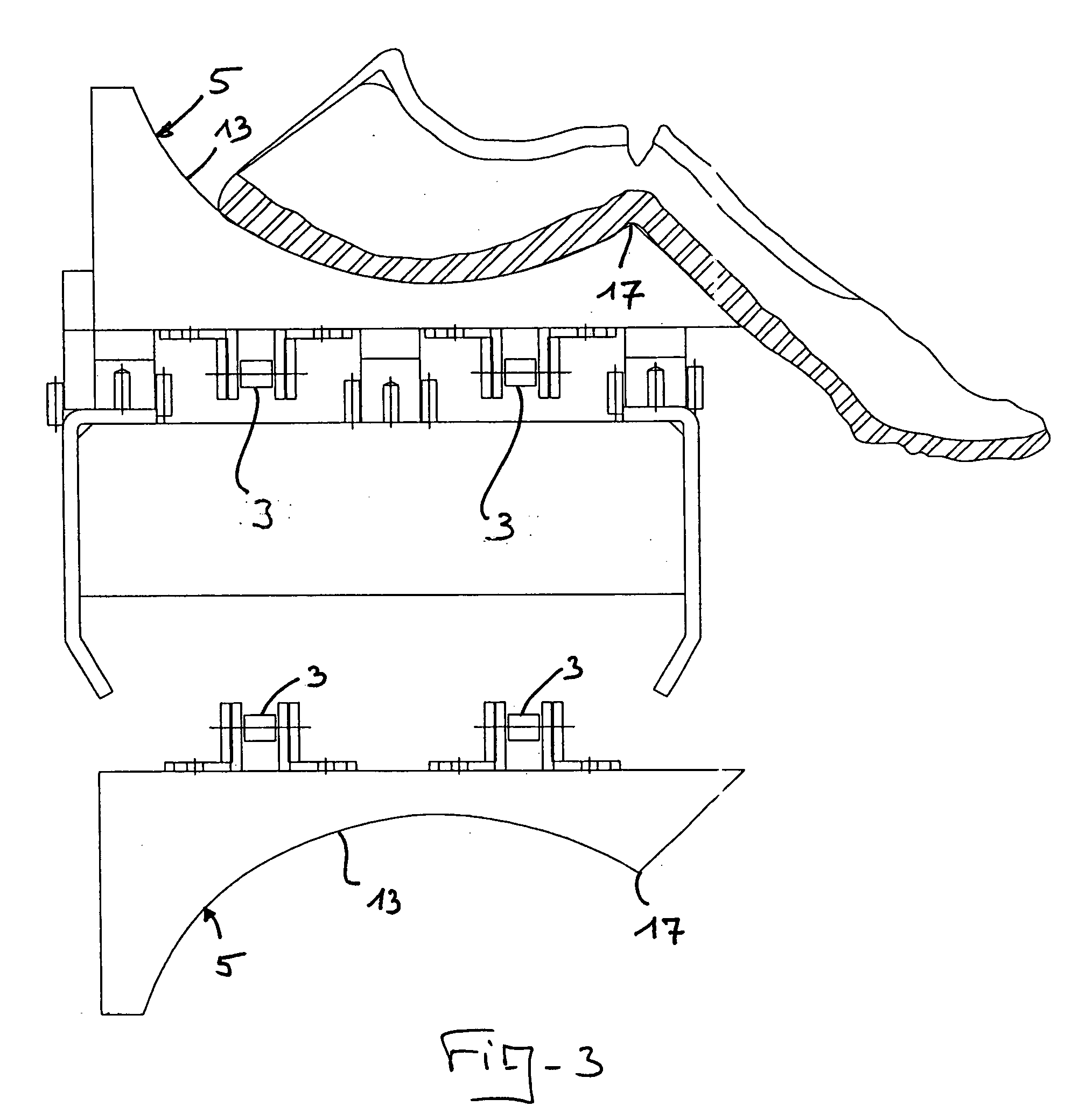
[0025] In the illustrated embodiment, the belt 1 comprises two driving chains 3 over the full length of which a plurality of modules are mounted in parallel relationship for supporting the loins. The modules are in the form of blocks 5 preferably made of rigid Nylon, which extends transversally to the chains 3 and are each provided with an upper surface 13 that is round-shaped and recessed in order to receive and hold the portion of the loins where is located the fat (see FIG. ...


PUM


Abstract

Disclosed is a belt for conveying loins attached to flanks in a loin puller equipment. This belt comprises one or more driving chains and a plurality of modules for supporting the loins, which are mounted in parallel relationship over all the length of the chains. These modules are in the form of blocks preferably made of rigid Nylon, which extend transversally to the chains and are provided with an upper surface that is round-shaped and recessed in order to receive and hold the parts of the loins where the fat is located. The blocks are advantageously interchangeable and then adaptable to the size of the loin to be cut. The belt is therefore easily modifiable as a function of the product to be processed. It is also easy to manufacture and install and much easier to maintain. The belt permits to convey loins that are not yet separated from the adjacent flanks without any risk of friction or scrapping, as is the case with the existing belt.

Description

FIELD OF THE INVENTION [0001] The present invention relates to a modular belt devised to be used in an equipment for automatically removing the backfat of a loin while said loin is still connected to a flank. BACKGROUND OF THE INVENTION [0002] In order to illustrate what are a loin and a flank and what is the kind of equipments that may be used for processing the same, reference can be made to U.S. Pat. No. 6,336,856 granted on Jan. 8, 2002 in the name of the Applicant. It is worth noting that the common name of this kind of equipment is “loin puller”. [0003] It is known in the food industry to use loin pullers for treating loins and flanks of pork. It is also well known that there are two kinds of loin pullers. The first one is devised to process a loin after it has been separated from the flank. The other one is devised to process a loin while it is still attached to the flank. [0004] The present invention especially applies to the second kind of equipment, which is disclosed in t...

Claims


Application Information

Patent Timeline
Patent Type & Authority Applications(United States)
IPC IPC(8): A22C18/00
CPCA22B5/0005B65G2201/02B65G17/10A22B5/161
Inventor DUFOUR, YVONCOUTURE, MARCELLORD, DANNYROY, JEAN-GUY
Owner G E LEBLANC
Why Eureka
Try Eureka