Method and system of controlling ultrasound systems

a control system and ultrasound technology, applied in the field of ultrasound systems, can solve the problems of difficult to predict the exact attenuation of the ultrasound wave when traveling through the body, the inability to properly compensate for the attenuation of the tissue, and the proportion of energy loss that is proportional to the distance traveled

Inactive Publication Date: 2006-02-09
GENERAL ELECTRIC CO
View PDF22 Cites 30 Cited by
  • Summary
  • Abstract
  • Description
  • Claims
  • Application Information

AI Technical Summary

Problems solved by technology

Further, such energy loss also is proportional to the distance traveled by the ultrasound wave.
Because the tissue attenuation coefficient varies among anatomies and body types (especially body with pathology) and the acoustic path an ultrasound wave travels within a body is often unpredictable, it is difficult to predict the exact attenuation an ultrasound wave experiences when traveling through the body.
If, during a clinical scan, a patient has a body type that is very different from an average body type, the internal TGC does not properly compensate for the tissue attenuation.
As a result, uneven brightness or banding artifacts may result in the displayed image.
However, such adjustment is usually imprecise and time consuming.
For example, because this adjustment requires human intervention, errors are more likely.

Method used


Image

  • Method and system of controlling ultrasound systems
  • Method and system of controlling ultrasound systems
  • Method and system of controlling ultrasound systems

Examples


Embodiment Construction

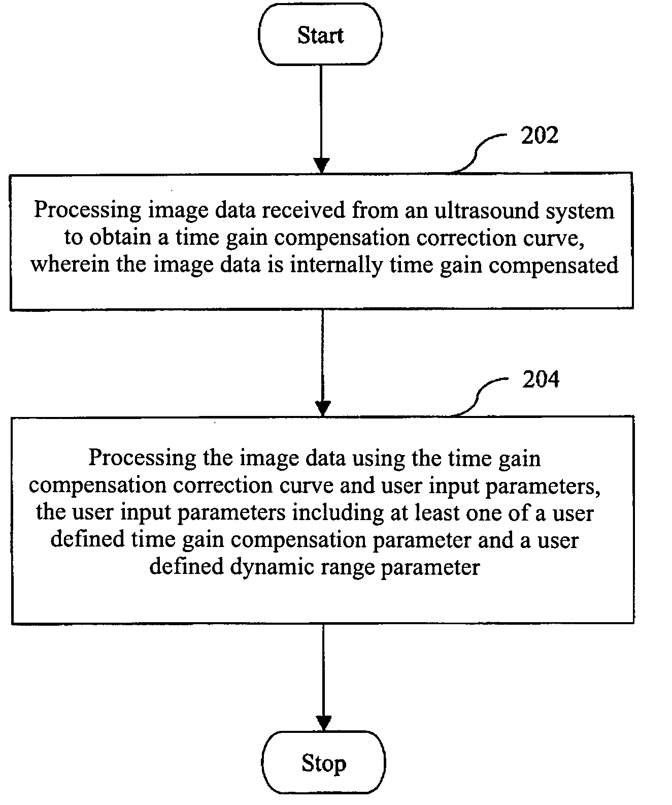
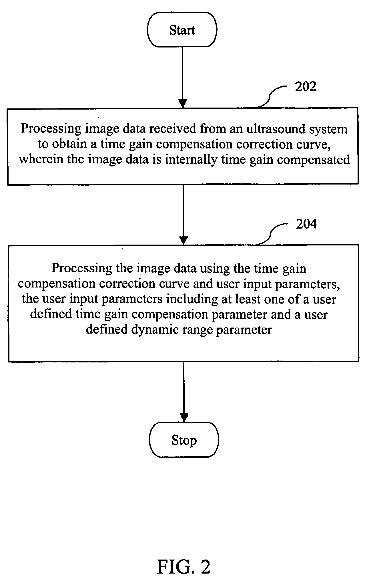
[0017] Various embodiments of an ultrasound system and a control method thereof are provided to automatically process internally time gain compensated image data to generate a TGC correction curve. Further, application of a user requested TGC curve is provided. Suppression of noise in the far-field and TGC curve correction during cine loop playback are also provided.

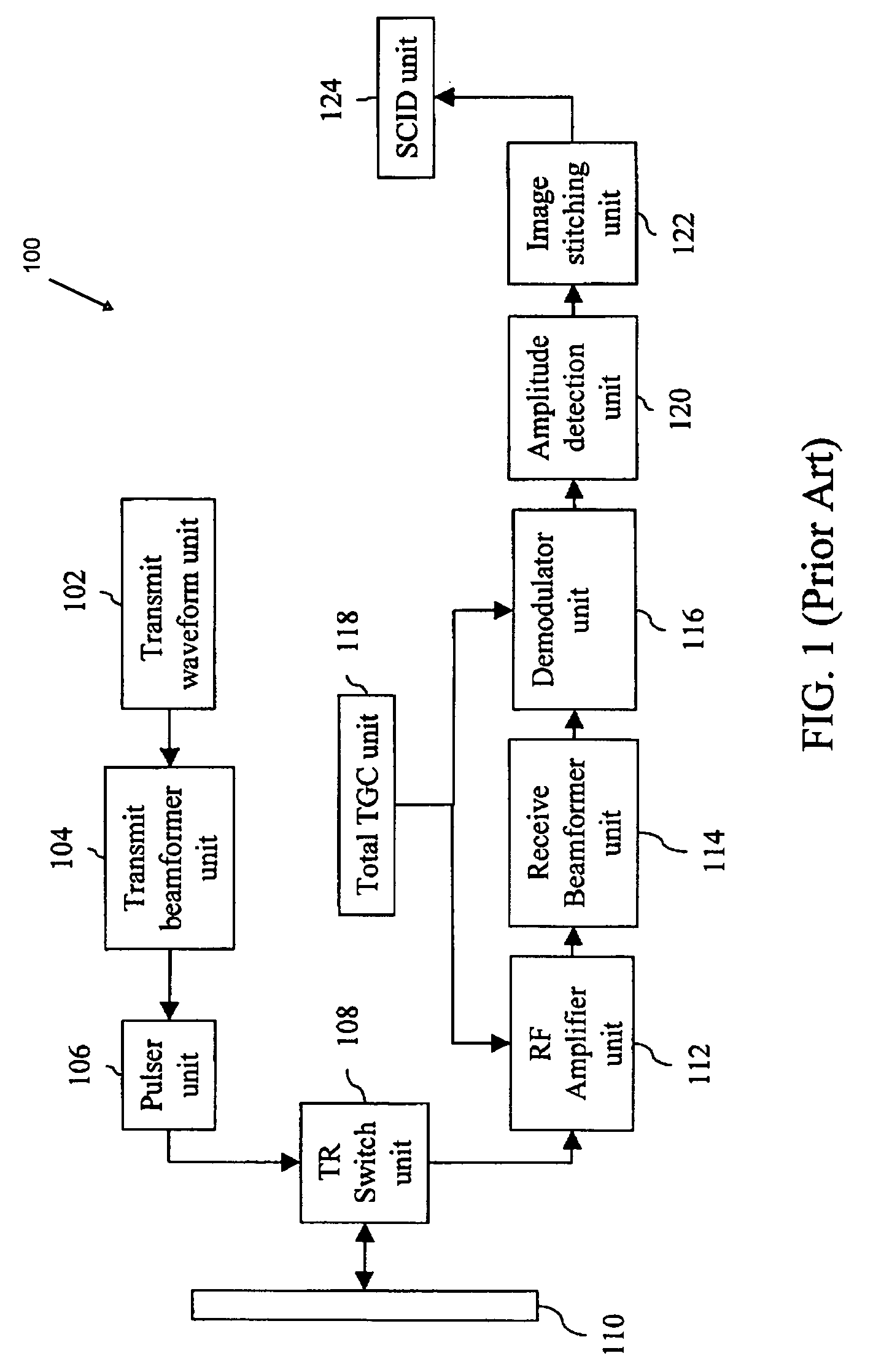
[0018]FIG. 1 is a block diagram illustrating an ultrasound system 100 configured to use a typical TGC curve. Ultrasound system 100 includes a transmit waveform unit 102, a transmit beamformer unit 104, a pulser unit 106, a Transmit / Receive switch (hereinafter referred to as a TR switch) unit 108, a transducer array 110, an RF amplifier unit 112, a receive beamformer unit 114, a demodulator unit 116, a total TGC unit 118, an amplitude detection unit 120, an image-stitching unit 122 and a Scan Conversion and Image Display (SCID) unit 124.

[0019] In various embodiments transducer array 110 comprises a plurality of separate...


PUM


Abstract

A method and system for controlling an ultrasound system are provided. The method includes processing image data received from an ultrasound system to obtain a time gain compensation correction curve, wherein the image data is internally time gain compensated. The method further includes processing the image data using the time gain compensation correction curve and user inputs parameters. The user input parameters include at least one of a user defined time gain compensation parameter and a user defined dynamic range parameter.

Description

BACKGROUND OF THE INVENTION [0001] This invention relates generally to ultrasound systems, and more particularly, to control of ultrasound systems using Time Gain Compensation (TGC). [0002] As an ultrasound wave travels through different layers of tissues, the amplitude of the wave decreases due to attenuation. Such energy loss is proportional to the tissue attenuation coefficient and the frequency of the ultrasound wave. Further, such energy loss also is proportional to the distance traveled by the ultrasound wave. Thus, echoes received from a tissue deeper in the body have less energy than those received from a similar tissue relatively closer to the surface of the body. For example, in Brightness mode (B-mode) grayscale imaging technique, the amplitude of a received echo is used to form an image. The brightness of a pixel in a B-mode image represents the strength of the corresponding echo. It is often desirable to display similar tissues with similar brightness, regardless of loc...

Claims


Application Information

Patent Timeline
Patent Type & Authority Applications(United States)
IPC IPC(8): A61B8/00
CPCG01S7/52033G06T5/009G06T2207/20092G06T2207/10132G06T5/40
Inventor ADAMS, QIAN ZHANGKULAKOWSKI, RICHARD MARIONWASHBURN, MICHAEL JOSEPH
Owner GENERAL ELECTRIC CO
Why Eureka
Try Eureka