
Thermal transition methods and devices

a transition method and material technology, applied in the direction of prosthesis, machines/engines, blood vessels, etc., can solve the problems of size and geometry, the precision with which stents may be placed and expanded, and the cost of balloon expansion capacity

Inactive Publication Date: 2006-02-09
DELEGGE REBECCA +1
View PDF19 Cites 110 Cited by
  • Summary
  • Abstract
  • Description
  • Claims
  • Application Information

AI Technical Summary

Benefits of technology

[0013] The method of thermal deployment described herein provides for controlled, ordered and sequential transition of a shape memory device through creating a line of demarcation between multiple temperature zones, each temperature zone selected corresponding to the two alternate temperature states (T<Mf and T>Af) of a shape memory device. The method provides for controll...

Problems solved by technology

Current methods of stent placement invariably involve introduction of a pre-formed stent across an obstructing lesion with limitation in the size and geometry of the stent mandated by its final form as the devices must be placed with a size nearly as great as their final deployed size.
Current stents may be expanded to a limited degree with balloon instrumentation however expansion is limited to less than a fifty percent increase over the placement dimension, furthermore the capacity for balloon expansion comes at the cost of having the stent proper composed of a relatively malleable material which may be subject to compression and re-stenosis with expansion of the obstructing lesion over time.
While these techniques and devices have afforded good clinical results, there remain limitations in anatomic locations where stents may be placed and the precision with which they may be positioned.
Relative size of pre-deployment and post deployment shapes likewise becomes a limiting factor in use of currently available designs and placement techniques.
Limitations of current techniques are largely due to re-obstruction secondary to overgrowth of tumor, accumulation of “bio-film”, or mechanical failure of the device maintaining patency for billiary drainage.
Furthermore, current systems are either permanent in placement or replaced only with extreme difficulty.
The operator must accurately choose the appropriate length of stent based upon information that cannot be directly measured; of necessity sizing information is gathered indirectly with fluoroscopic imaging or direct visualization through an endoscope with both methods subject to inaccuracies.
No current billiary stenting systems are available having variable length capabilities.

Method used


Image

  • Thermal transition methods and devices
  • Thermal transition methods and devices
  • Thermal transition methods and devices

Examples


Embodiment Construction

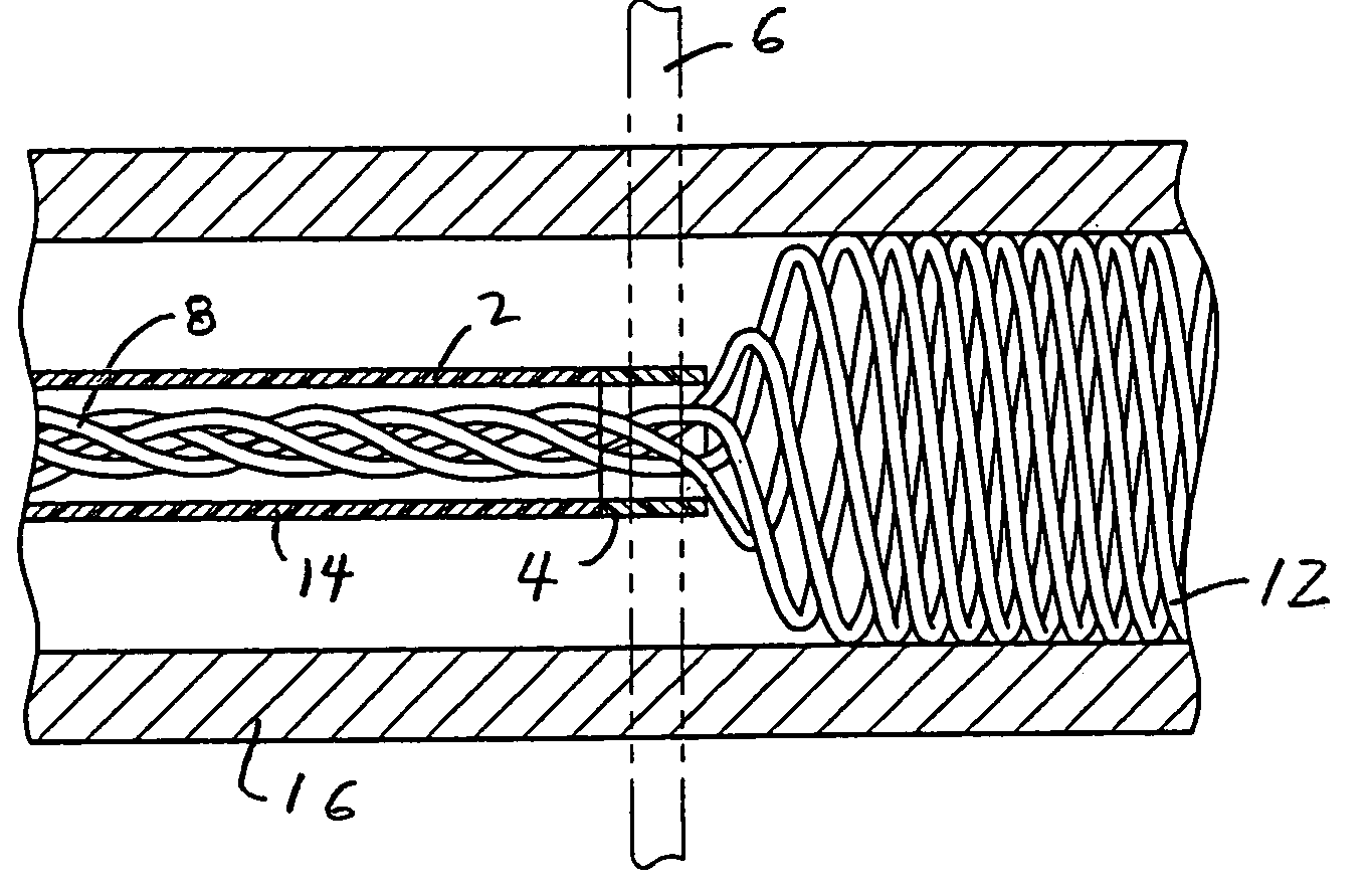
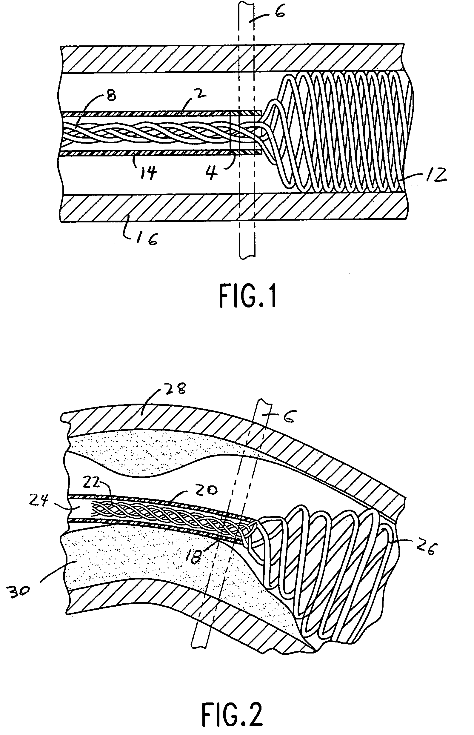
[0029] In the preferred embodiment, differing temperature environments are created and thermally isolated. The shape memory device undergoing transition is spatially translocated between a first temperature zone 2 and a second temperature zone 4. FIG. 1. Transition of the geometry of the shape memory material device 8 occurs in a spatially defined zone 6. The transitioned shape memory device 12 exits the thermal activation device 14 after transition. Once the device has undergone transition its temperature remains at or above (or below) the limits of transition so that there is no uncontrolled return to alternate temperature form. The transition occurs with the thermal activation device in situ so that the transitioned thermally active device is in position for use. As shown, the transitioned thermal activation device is present in a lumen 16. Other in situ applications for the process exist.

[0030] The method utilizes a defined space having a temperature maintained at or below eith...


PUM

PropertyMeasurementUnit
Temperatureaaaaaaaaaa
Electrical resistanceaaaaaaaaaa
Mechanical forceaaaaaaaaaa

Abstract

A method of sequentially transitioning a thermally active shape memory device progressively translocates the thermally active shape memory device through a first controlled temperature zone and through an additional controlled temperature zone. The thermally active shape memory device is thermally transitioned and changed in geometric shape as a result of thermal communication of the shape memory device with either or both of the controlled temperature zones to produce a transitioned thermally active shape memory device. Novel devices produced according to the method are also disclosed.

Description

[0001] Applicant claims the benefit of U.S. Provisional Application Ser. No. 60 / 598,920 filed Aug. 4, 2004. [0002] Applicant claims the benefit of U.S. Provisional Application Ser. No. 60 / 627,302 filed Nov. 12, 2004. [0003] Applicant claims the benefit of U.S. Provisional Application Ser. No. 60 / 664,362 filed Mar. 23, 2005.FIELD OF THE INVENTION [0004] This invention relates to temperature dependent transition of shape memory materials. BACKGROUND OF THE INVENTION [0005] Shape memory materials (particularly those of nitinol and various nitinol like alloys) have physical properties that may be varied dependent upon the temperature of the immediate environment in which the memory device exists. For nitinol alloys two forms are described: Martensite, which is the low temperature form generally may be thought of as a malleable metal; and Austenite, a high temperature form which exhibits properties of shape memory and super-elasticity. The transition between two forms of nitinol is chara...

Claims


Application Information

Patent Timeline
IPC IPC(8): A61F2/06A61F2/844A61F2/86
CPCA61B2017/00867A61B2017/1205A61F2/844A61F2/86A61F2210/0014A61B2017/12077A61F2/88A61F2210/0033A61F2210/0076A61B2017/12054C22F1/006
Inventor DELEGGE, REBECCAKITCHEN, MICHAEL S.
Owner DELEGGE REBECCA
Learn More