Temperature-switching materials having improved strength and thermal properties

a technology of temperature switching materials and thermal properties, which is applied in the direction of temperature measurement in household appliances, polishing compositions, other chemical processes, etc., can solve the problems of inconvenient use in medical or food industries, inconvenient use of low melting eutectic alloys, and inability to meet the requirements of the application of the actuator device, so as to achieve the effect of increasing mechanical strength

Active Publication Date: 2012-09-11
VOLK ENTERPRISES A DELAWARE US CORP
View PDF12 Cites 7 Cited by
  • Summary
  • Abstract
  • Description
  • Claims
  • Application Information

AI Technical Summary

Benefits of technology

[0020]In a related aspect, a thermoresponsive switching material (TSM) composition is provided, having increased mechanical strength and a narrow melting temperature range comprising: from about 80% to about 99% of a first crystalline, non polymeric, low molecular weight organic compound (LMWOC) based material having an melting point spread of about 10° C., and from about 1% to about 20% of a strengthening agent, wherein the thermoresponsive switching material has a mechanical strength below it's melting temperature that is at least 10% greater than the mechanical strength of the first crystalline, non polymeric, low molecular weight organic compound-based material.

Problems solved by technology

However, there are few eutectic metal alloys that have a melting temperature in this temperature range.
In addition, eutectic metal alloys such as, e.g., lead / cadmium mixtures, have inherent toxicity and may not be suitable for use in the medical or food industries.
Low melting eutectic alloys are also costly.
Similarly, there are few organic compounds that have melting points in the temperature range of interest, and of those that do have a suitable melting point often possess a physical or chemical property that renders the material toxic or otherwise undesirable for use in an actuator device.
A further problem with existing metallic and organic compounds is that it is not possible to vary the melting point, while at the same time maintaining abrupt melting behavior (i.e., a sharp melting curve).
Many organic compounds that have sharp melting points do not provide the mechanical properties for use in a thermo-mechanical device.

Method used


Image

  • Temperature-switching materials having improved strength and thermal properties
  • Temperature-switching materials having improved strength and thermal properties
  • Temperature-switching materials having improved strength and thermal properties

Examples


example 1

Formulations

[0103]The formulations shown in Table 1 were prepared using standard methods. Transition temperature, spread, and structural integrity data were obtained using the formulations in exemplary disposable temperature indicator devices. Structural integrity was determined using a pull test, wherein the plunger / stem was pulled with a hanging weight while the barrel was secured in a fixed position (see, e.g., U.S. Pat. No. 7,204,199; Volk Enterprises, Inc. (Turlock, Calif.)). Where present, numbers in parenthesis in Table 1 indicate the overall composition of the formulation. Additional information relating to strengthening agents is shown in Table 2.

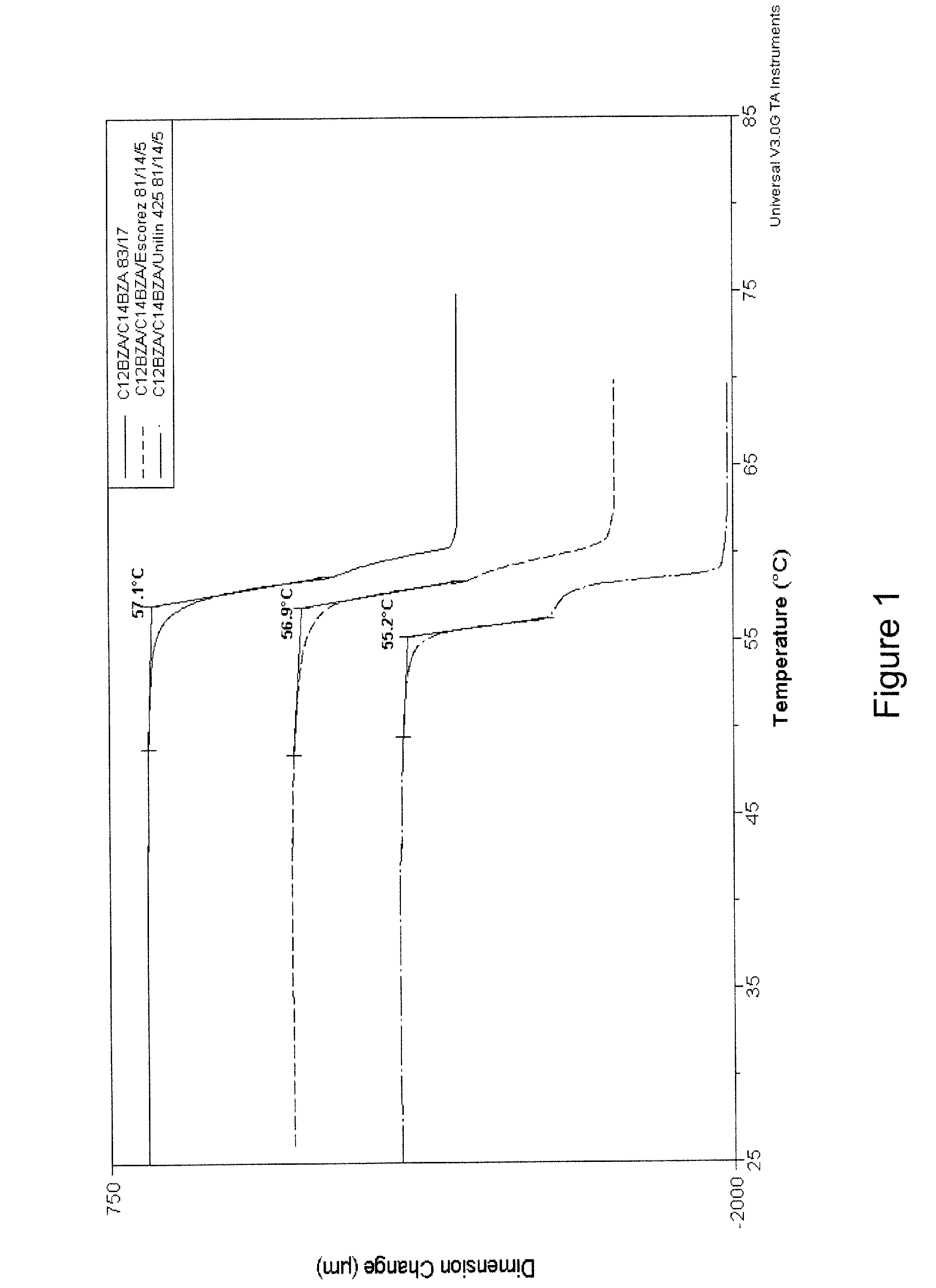
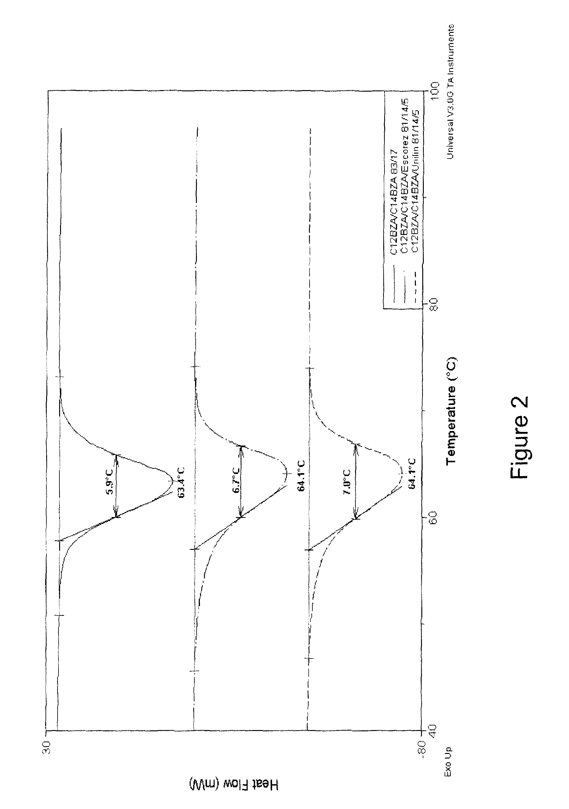
[0104]DSC and TMA analyses were performed on some formulations using a Universal V3.0G TA Instrument. The results generally agreed with those obtained using the disposable temperature indicator devices. Exemplary DSC and TMA results are shown in FIG. 1-4.

[0105]

TABLE 1Exemplary TSM compositionsDevice PropertiesCompound PropertiesFir...

example 2

Temperature Indicator / Monitoring Device

[0107]An exemplary temperature indicator / monitoring devices is described in U.S. Pat. No. 5,799,606 and illustrated in FIG. 5A-5H. Referring first to FIGS. 5A and 5B, such devices 10 generally include an elongate device / thermometer housing 11 having a pointed tip 12 and a transversely-extending flange 13 formed opposite the tip 12. The upper surface of the flange 13 is preferably substantially planar. A plurality of barbs 14 are formed on the exterior of the housing 11. The shape, size and number of exterior barbs 14 may vary as desired (two are exemplified). The device 10 may be inserted into poultry, meat, or other products by positioning the pointed tip 12 against the product and pressing the thermometer 10 inwardly until the underside of flange 13 engages the outer surface of the product. The barbs 14 securely hold the temperature indicating device 10 in place during storage, handling and cooking of the product.

[0108]The housing 11 is forme...

example 3

Temperature Indicator / Monitoring Device

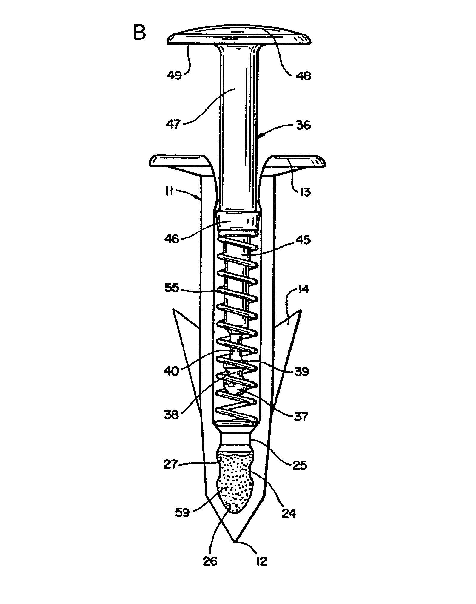
[0125]Another exemplary temperature monitoring device is described in U.S. Pat. No. 7,204,199 and illustrated in FIGS. 6A-6D. The device 10 includes barrel 12, which is a monolithic molded body made of a material capable of withstanding the elevated temperatures encountered in a cooking environment. Nylon is an exemplary material, although other materials could be adapted for use in the cooking environment as well. The barrel 12 includes lower barrel end 14 adapted for insertion into a food item, and which may be provided with one or more barbs 20 radially disposed near lower barrel end 14 for retaining the temperature monitoring device 10 in the food once inserted. Barrel 12 also includes annular flange 16 located adjacent upper barrel end 18. Flange 16 may be of varying radial dimensions so as to contact the surface of the food item when the device 10 is inserted therein to prevent further insertion.

[0126]Barrel 12 communicates with cavity 24...


PUM

PropertyMeasurementUnit
melting pointaaaaaaaaaa
molecular weightaaaaaaaaaa
melting temperatureaaaaaaaaaa

Abstract

The subject matter described herein relates to thermoresponsive switching materials that undergo a thermal transition over a narrow temperature range and to devices, such as actuators, indicators, and sensors, prepared from such compositions.

Description

PRIORITY[0001]This application claim priority to U.S. Provisional Application Ser. Nos. 60 / 997,347, filed on Oct. 1, 2007, and 61 / 063,285, filed on Feb. 1, 2008, which are hereby incorporated by reference in their entirety.TECHNICAL FIELD[0002]The subject matter described herein relates to temperature switching materials that undergo a thermal transition over a narrow temperature range and to devices, such as actuators, indicators, and sensors, prepared from such compositions.BACKGROUND[0003]A variety of devices in a wide range of industries include one or more components prepared from a material that undergoes a phase change at a temperature of interest. The phase change alters the physical properties of the component part, which typically alters the way other components in a device are positioned or interact. For example, in response to a phase change in a structural component of a device, related components may expand or contract, inducing a reaction, such as movement of an adjac...

Claims


Application Information

Patent Timeline
Patent Type & Authority Patents(United States)
IPC IPC(8): G01N31/22
CPCF03G7/06G01K11/06G01K2207/06
Inventor STEWART, RAY F.DUNSON, DEBRA L.
Owner VOLK ENTERPRISES A DELAWARE US CORP
Why Eureka
Try Eureka