Voltage collapse diagnostic and ATC system

a voltage collapse and diagnostic technology, applied in the field of voltage collapse diagnostic and atc system, can solve the problems of voltage collapse, overload of additional power system components, and cascading loss of stability, and achieve the effect of improving or reducing reliability

Inactive Publication Date: 2006-02-09
INTELILCON
View PDF13 Cites 34 Cited by
  • Summary
  • Abstract
  • Description
  • Claims
  • Application Information

AI Technical Summary

Benefits of technology

[0008] The present invention provides Available Transfer Capability, which is an active power constraint that indicates when the electrical power system has too much power being imported into a load bearing agent or the control region used to arrest blackouts after single and double outages. The present invention also provides Voltage Collapse Diagnostic and Preventive Control, which indicates the single and single outage components of double outages that could cause blackout for any control region, the control region agents where Preventive Control may be preventing the blackouts for these outages, and the maximum amount of power that can be imported into the control region without causing blackout for any of the single equipment outages. All of the above including

Problems solved by technology

A number of problems can arise when outages occur within an electrical power system.
One kind of problem, called voltage collapse, is a cascading loss of stability.
The loss of stability typically originates in one or more subsystems of the electrical power system (caused by an equipment outage or increased load) which in turn, overloads additional power system components.
Voltage Collapse can also be caused by an equipment outage due to relaying actions, failure of equipment, or failure of control.
Typically, voltage collapse leads to a blackout or brownout where customers are no longer provided with the power they desire.
Another type of voltage problem, called loss of voltage stability, is the inability of the generation, transmission, and distribution system to supply enough power to satisfy customer demand after a disturbance, increased load, or a change in operating conditions without an uncontrollable and progressive decrease in voltage.
The sou

Method used


Image

  • Voltage collapse diagnostic and ATC system
  • Voltage collapse diagnostic and ATC system
  • Voltage collapse diagnostic and ATC system

Examples


example 1

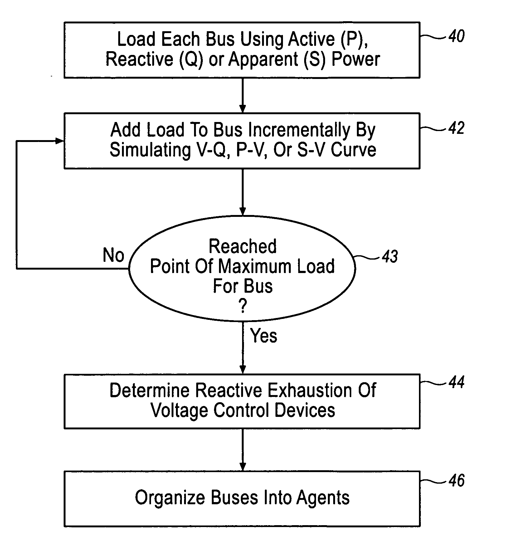
[0078] By way of a non-limiting hypothetical example, the above-described process is explained in conjunction with an example based on the Tables set forth below. In Table 1, the leftmost column identifies each specific bus of an area in the determined region of interest and buffer zone in the electrical power system that is under study. The middle column in Table 1 defines the actual loads on the respective buses listed in the Table. The rightmost column defines the reactive reserves or generators that are depleted at the point of maximum load for the specific bus using a stress test such as a VQ curve. For the purpose of this example, reactive reserves are listed only as generators. The generators A, B, C, D, and E referenced in the Table correspond to the generators listed in FIG. 5.

TABLE 1Reactive Reserves of busesBus #Real Load (MW)Gens Exhausted115A20B30B4100A, C50A, B60A710A, B, C830B, D940B, D10200E110B, D, E1210A

[0079] The results in Table 1 above are used to group buses ...

example 2

[0106] Referring now to the tables illustrated below, a hypothetical non-limiting example is illustrated that will use the agents as defined in Table 2 and diagrammed in FIG. 5 as well as a set of single contingencies that are defined by the letters A-F as discussed above. Each letter represents a single contingency or piece of electrical equipment that can be switched off and effectively removed from the electrical system. This example asserts that the (1) Voltage Collapse Diagnostic is performed as outlined in previous sections to obtain the agents from Table 2 and FIG. 5, (2) single contingency analysis is performed to find if any single outages cause voltage collapse and find those outages that are used to find the double outages that will be simulated, (3) double contingency analysis is performed for determining the set of double outages to be simulated by selecting X and N and (4) by simulation of the resulting set of double contingencies produced out of single outage combinat...

example 3

[0117] This hypothetical-non-limiting example will also use the agents as defined in Table 2 and diagrammed in FIG. 5 as well as a set of single contingencies that are defined by the letters A-F. As in Example 2, each letter represents a single piece of electrical equipment that can be switched off and effectively removed from the electrical system. These single contingencies are intended to be a set independent of those in Example 2. This example asserts that the Voltage Collapse Diagnostic is performed as outlined in previous sections to obtain the agents from Table 2 and FIG. 5 and single contingency analysis is performed. From this single contingency analysis, it is determined that the single contingencies represented by the set A, C and E do not reach solutions to the load flow equations when the maximum percentage of the outage remaining in the system is equal to zero and are thus problematic single contingencies. Preventive Loadshedding Control is then performed on these sing...


PUM


Abstract

The present invention provides an analysis method for an electrical power system whereby the plurality of buses are grouped into agents, family lines of agents and families of agents based on the reactive reserves depleted when the buses are loaded. Contingencies are then applied to the electrical power system and the reactive reserves are monitored and an exhaustion factor is determined for one or more family lines in one or more families. A method for selecting double outage that have no solution for each outage that has no solution when the outage is removed in small steps and an additional step has no solution. The boundary case solution is used to assess where, why, and how the contingency causes voltage instability, voltage collapse, and local blackout. Based on this information, the design of voltage rescheduling, active rescheduling, unit commitment, load shedding is determined that can be used as preventive, corrective, or emergency controls in applications such as system design and planning, operation planning, reactive and voltage management, real time control, and Special Protection System Control. Based on this information, solutions can then be applied to the political power system.

Description

RELATED APPLICATIONS [0001] This application is a continuation-in-part of U.S. application Ser. No. 10 / 879,236 filed Jun. 28, 2004.TECHNICAL FIELD [0002] This invention relates generally to system design and planning, scheduling operation, real time control, and protection of electrical power systems, and more particularly, this invention relates to methods for predicting actual or imminent electrical power system failure due to voltage collapse, local blackout, or voltage instability. BACKGROUND [0003] A number of problems can arise when outages occur within an electrical power system. One kind of problem, called voltage collapse, is a cascading loss of stability. The loss of stability typically originates in one or more subsystems of the electrical power system (caused by an equipment outage or increased load) which in turn, overloads additional power system components. Voltage Collapse can also be caused by an equipment outage due to relaying actions, failure of equipment, or fai...

Claims


Application Information

Patent Timeline
IPC IPC(8): H02J3/00
CPCH02J3/00H02J2003/001Y02E60/76Y04S40/22H02J2003/007H02J2203/20Y02E60/00Y04S40/20H02J3/0012
Inventor SCHLUETER, ROBERTMINSHALL, BENJAMIN A.HUNT, RYAN J.
Owner INTELILCON
Why Eureka
Try Eureka