Supercharge Your Innovation With Domain-Expert AI Agents!

Direct injection internal combustion engine

a technology of internal combustion engine and fuel injection valve, which is applied in the direction of combustion engine, engine cooling apparatus, machines/engines, etc., can solve the problems of internal combustion engine not being able to efficiently stratify charge, deteriorating the capability of the fuel injection valve to inject fuel, and difficult to provide a cooling channel between the fuel injection valve and the spark plug

Inactive Publication Date: 2006-02-16
NISSAN MOTOR CO LTD
View PDF12 Cites 8 Cited by
  • Summary
  • Abstract
  • Description
  • Claims
  • Application Information

AI Technical Summary

Benefits of technology

[0008] It is an object of the present invention to provide a direct injection internal combustion engine of a center injection type which is capable of cooling a fuel injection valve effectively by a large cooling channel formed between the fuel injection valve and a spark plug.

Problems solved by technology

This causes coking of the fuel to be deposited on inside and outside parts of the fuel injection valve, and thereby deteriorates capability of the fuel injection valve to inject the fuel.
As a result, the above-mentioned internal combustion engine may not be able to perform an efficient stratified charge operation.
In the above-mentioned internal combustion engine of earlier technology, however, the spark plug is disposed beside the fuel injection valve, and it is therefore difficult to provide a cooling channel between the fuel injection valve and the spark plug.
If it is possible to provide a cooling channel between the fuel injection valve and the spark plug, such cooling channel would have a small width and be located far from an end portion of the fuel injection valve, and thus could not sufficiently cool the end portion of the fuel injection valve.
However, because of a fuel line provided above the fuel injection valve, and a high-tension cable or an ignition coil provided above the spark plug, the fuel line and the high-tension cable or the ignition coil of adjacent cylinders may interfere with each other.
As heretofore described, it is difficult for such direct injection internal combustion engine of earlier technology to sufficiently cool the end portion of the fuel injection valve.

Method used


Image

  • Direct injection internal combustion engine
  • Direct injection internal combustion engine
  • Direct injection internal combustion engine

Examples


Embodiment Construction

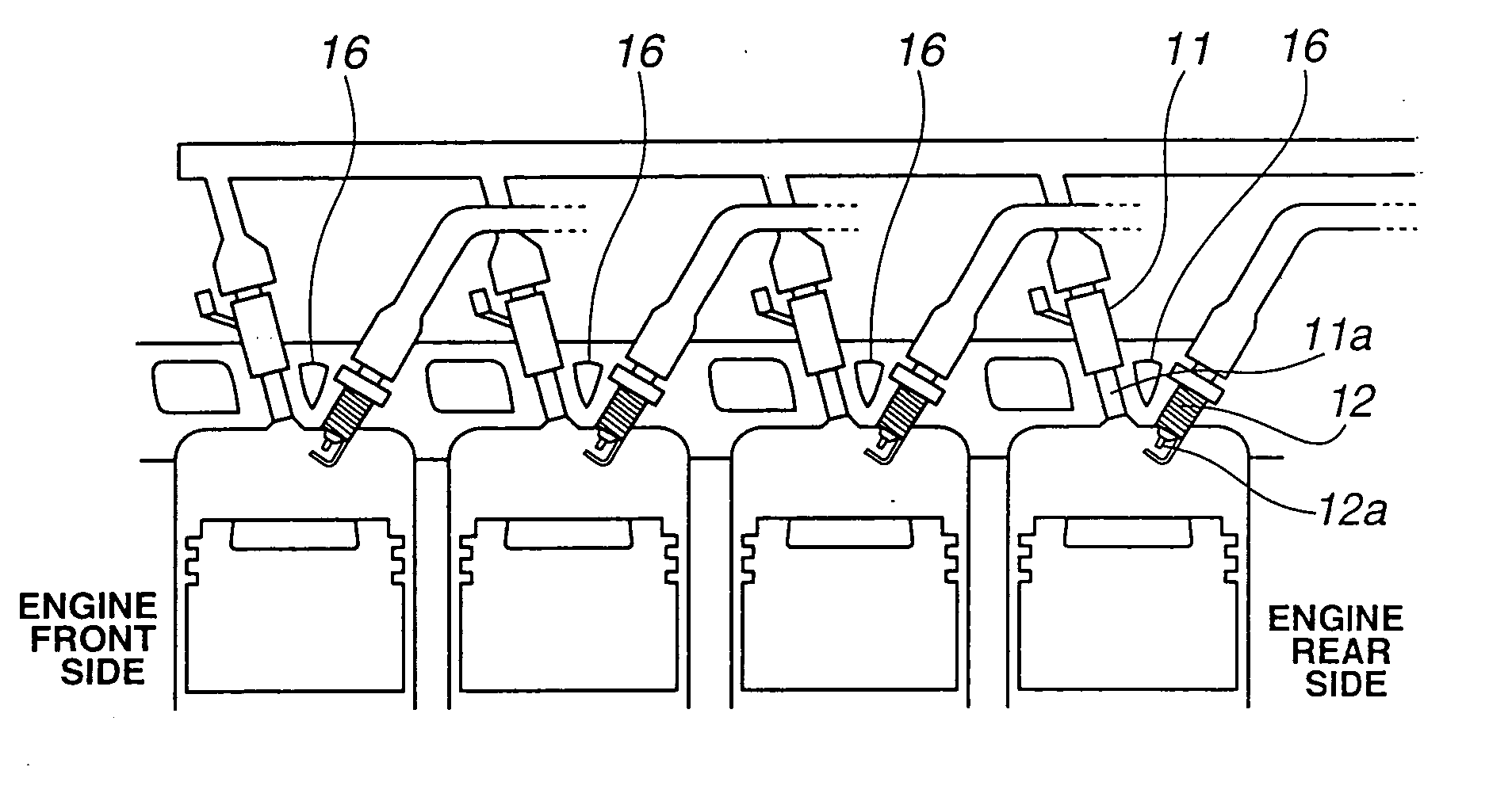
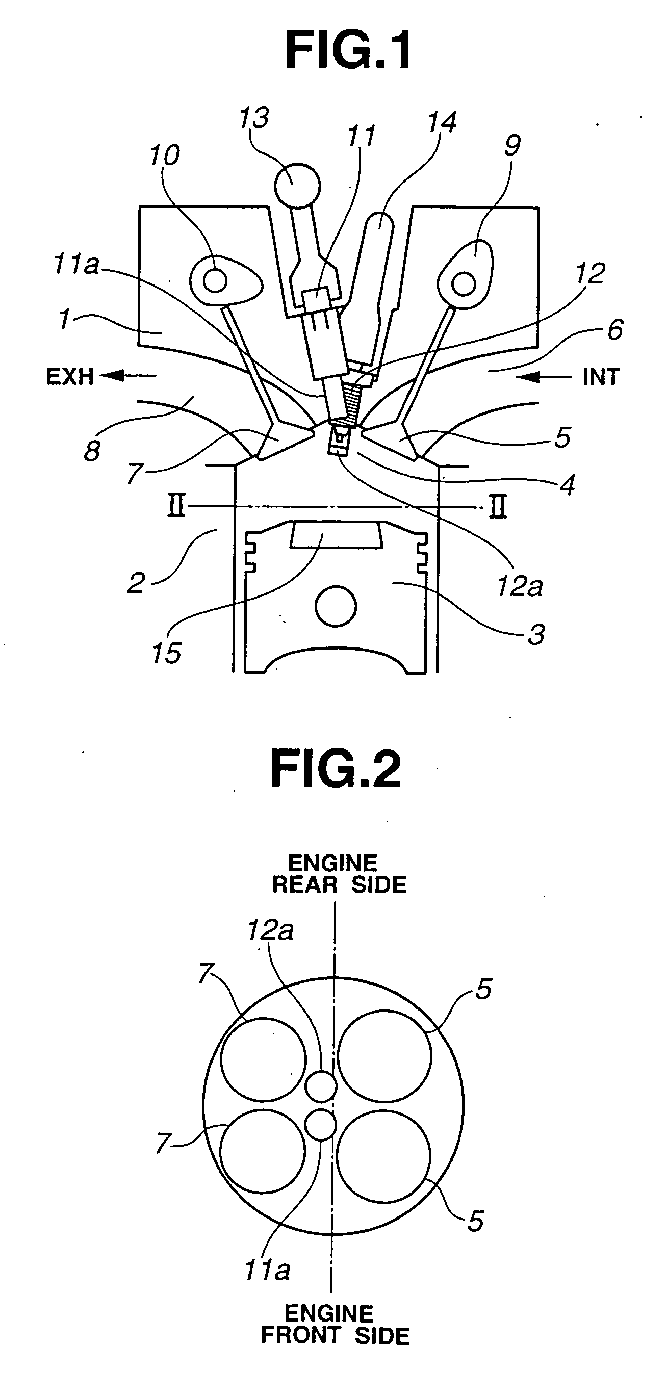
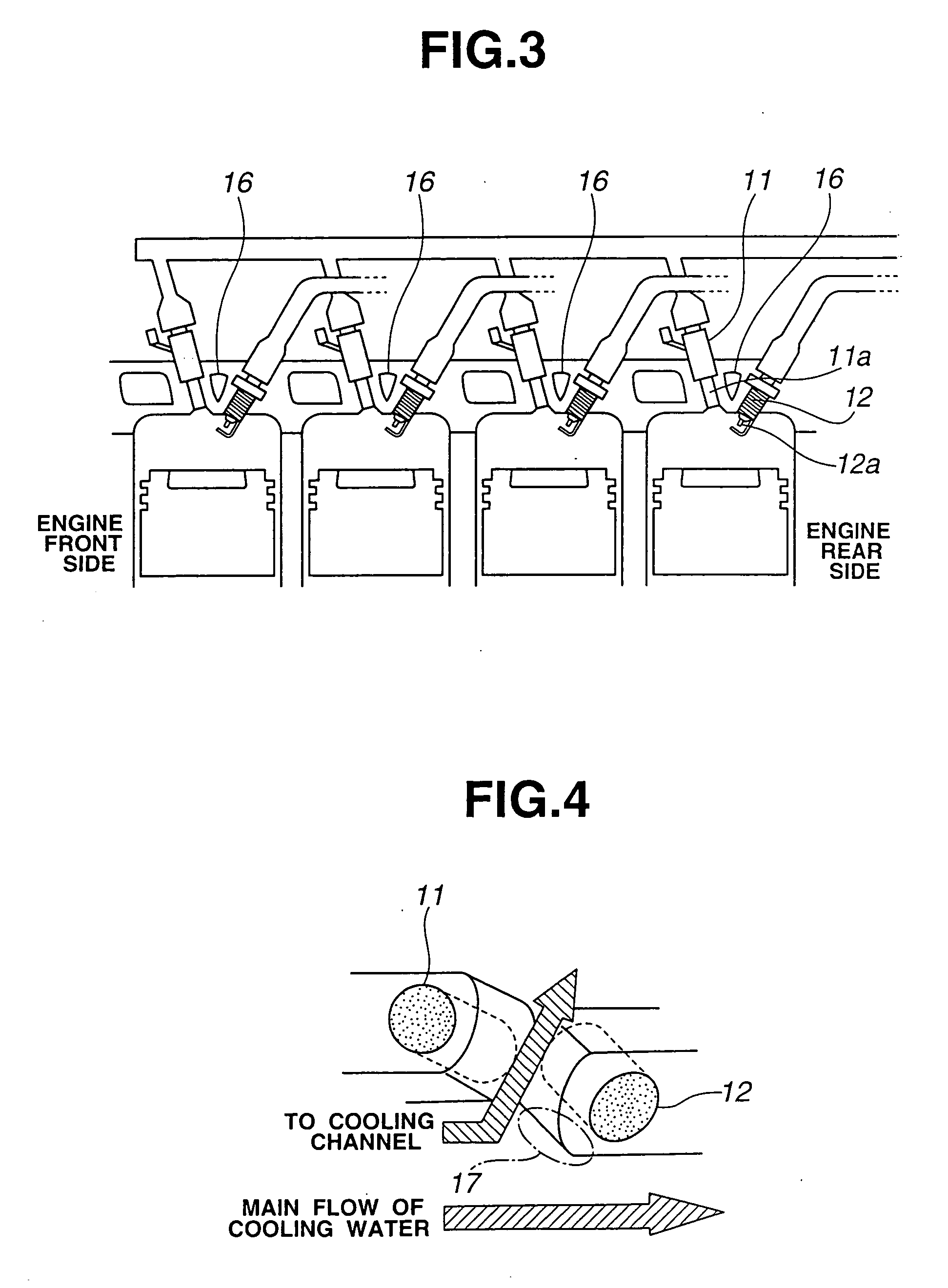
[0014]FIG. 1 is a view showing a direct injection internal combustion engine according to an embodiment of the present invention, as viewed from front of the engine. FIG. 2 is a sectional view taken along a line II-II in FIG. 1, as viewed from downward of the engine. FIG. 3 is a view showing the direct injection internal combustion engine of FIG. 1, as viewed from side of the engine.

[0015] The direct injection internal combustion engine of this embodiment includes a cylinder head 1 and a cylinder block 2 forming a plurality of cylinder portions or cylinders arranged in a cylinder arrangement direction. Each of the cylinder portions includes a piston 3, intake valves 5, intake ports 6, exhaust valves 7, and exhaust ports 8. Cylinder head 1, cylinder block 2 and piston 3 define a combustion chamber 4. Cylinder head 1 forms an upper surface of combustion chamber 4. Combustion chamber 4 communicates with intake ports 6 and exhaust ports 8 respectively via intake valves 5 and exhaust va...


PUM


Abstract

In a direct injection internal combustion engine, a fuel injection valve and a spark plug of adjacent cylinders are inclined at different angles from each other in directions perpendicular to a cylinder arrangement direction in which the cylinders are arranged. Besides, the fuel injection valve and the spark plug of at least one of the cylinders are inclined at different angles from each other in directions parallel to the cylinder arrangement direction. A cooling channel is provided between the fuel injection valve and the spark plug of the at least one of the cylinders.

Description

BACKGROUND OF THE INVENTION [0001] The present invention relates to a direct injection internal combustion engine of a center injection type in which a fuel injection valve and a spark plug are disposed at a middle part of an upper part of a combustion chamber. [0002] In a spark ignition combustion, fuel is injected directly from a fuel injection valve into a cylinder to form a stratified air-fuel mixture in the cylinder. An internal combustion engine thereby performs a wide-ranging lean burn or combustion. Such internal combustion engine can largely reduce a fuel consumption especially in a low / intermediate-load combustion. [0003] Japanese Patent Application Publication No. H11(1999)-22592 discloses a direct injection internal combustion engine of a center injection type in which a fuel injection valve is disposed at a middle part of an upper part of a combustion chamber, and a spark plug is directed toward a central part of the combustion chamber. In such direct gasoline-injection...

Claims


Application Information

Patent Timeline
IPC IPC(8): F01P1/10F02B3/02F02B23/10
CPCY02T10/125F02B23/101Y02T10/12
Inventor TAYAMA, AKIRATSUCHIDA, HIROFUMIHIRAYA, KOJIMATAYOSHI, YUTAKA
Owner NISSAN MOTOR CO LTD
Features
  • R&D
  • Intellectual Property
  • Life Sciences
  • Materials
  • Tech Scout
  • Unparalleled Data Quality
  • Higher Quality Content
  • 60% Fewer Hallucinations
Learn More