Method and a device for detecting an abnormality of a heat exchanger and the use of such a device

a technology of abnormality and heat exchanger, which is applied in the direction of material thermal analysis, lighting and heating apparatus, steam/vapor condensers, etc., can solve the problems of reduced heat exchange, insufficient fluid flow, and increased power consumption, so as to reduce the sensibility to fluctuations

Inactive Publication Date: 2006-02-16
DANFOSS AS
View PDF46 Cites 30 Cited by
  • Summary
  • Abstract
  • Description
  • Claims
  • Application Information

AI Technical Summary

Benefits of technology

[0008] It is an object of the present invention to provide a method to enable early detection of an abnormality of a heat exchanger.
[0014] employing the estimated second fluid outlet temperature for evaluating the heat exchange between the first and second fluids by comparing the estimated second fluid outlet temperature, or a parameter derived therefrom, with a reference value. By this method is provided a convenient way of assessing the functioning of the heat exchanger primarily based on parameters of the first fluid, which means that a minimum of sensors are needed for providing information regarding the second fluid, and an automatic detection of heat exchanger abnormality is made possible. Further this method makes it possible to detect restricted flow as well as fouling of the heat exchanger.

Problems solved by technology

This may be due to fouling of heat exchanger, in that a layer of scale, dirt or grease is deposited on the heat exchanging surface or surfaces leading to reduced heat exchange, as this layer will usually act as an insulating layer.
Another possibility is that there is insufficient fluid flow because of dirt or the like blocking or restricting flow through the heat exchanger.
Both situations lead to higher power consumption, because the system must work at a higher load than a system working with heat exchangers within the normal range.
Further in the event of adverse working conditions with high heat exchange demand and a relatively small temperature difference between the fluids, it may be impossible to meet the demand, which in some systems may have devastating effect.
Often the abnormality will not be detected before an adverse working condition is experienced, in that the demand cannot be met, e.g. leading to an increase of the temperature of a system, which should be kept at a specific temperature.
An example of such a system is a refrigerated display cabinet in a shop, where strict legislation in most countries prescribes that when food is not kept below a maximum temperature, it must be discarded, which of course is expensive and devastating for the business.
Likewise large computer systems are often kept in air-conditioned rooms, as an excessive temperature may increase the risk of a computer crash, which may entail a high risk of data loss and lost man-hours.
Often the heat exchangers are placed so inspection is difficult, and hence such inspection is labour consuming.
Further an abnormality may arise at different intervals and quite quickly, e.g. in the event of material blocking the inlet to the heat exchanger.
Further a visual inspection of the outside of the heat exchanger may not be effective in assessing whether the internal heat exchanging surfaces are subject to fouling etc. causing a reduced heat exchange.
It has also been proposed to assess the flow based on pressure sensors, but such pressure sensors are also expensive, and to gain useful information on the overall flow field a plurality of pressure sensors should be used.
A further disadvantage of these methods are that they can only be used to establish if there is restricted flow in the heat exchanger, not the situation where the flow is normal, but heat exchange is reduced, e.g. because of fouling of the heat exchanger surface.

Method used


Image

  • Method and a device for detecting an abnormality of a heat exchanger and the use of such a device
  • Method and a device for detecting an abnormality of a heat exchanger and the use of such a device
  • Method and a device for detecting an abnormality of a heat exchanger and the use of such a device

Examples


Embodiment Construction

[0039] In the following reference will be made to a heat exchanger in a simple refrigeration system, although the principle is equally applicable to a heat exchanger in other heat exchanging systems, and as understood by the skilled person, the invention is in no way restricted to a refrigeration system.

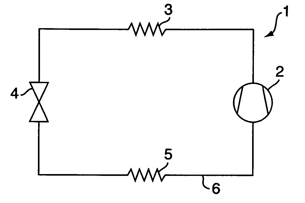
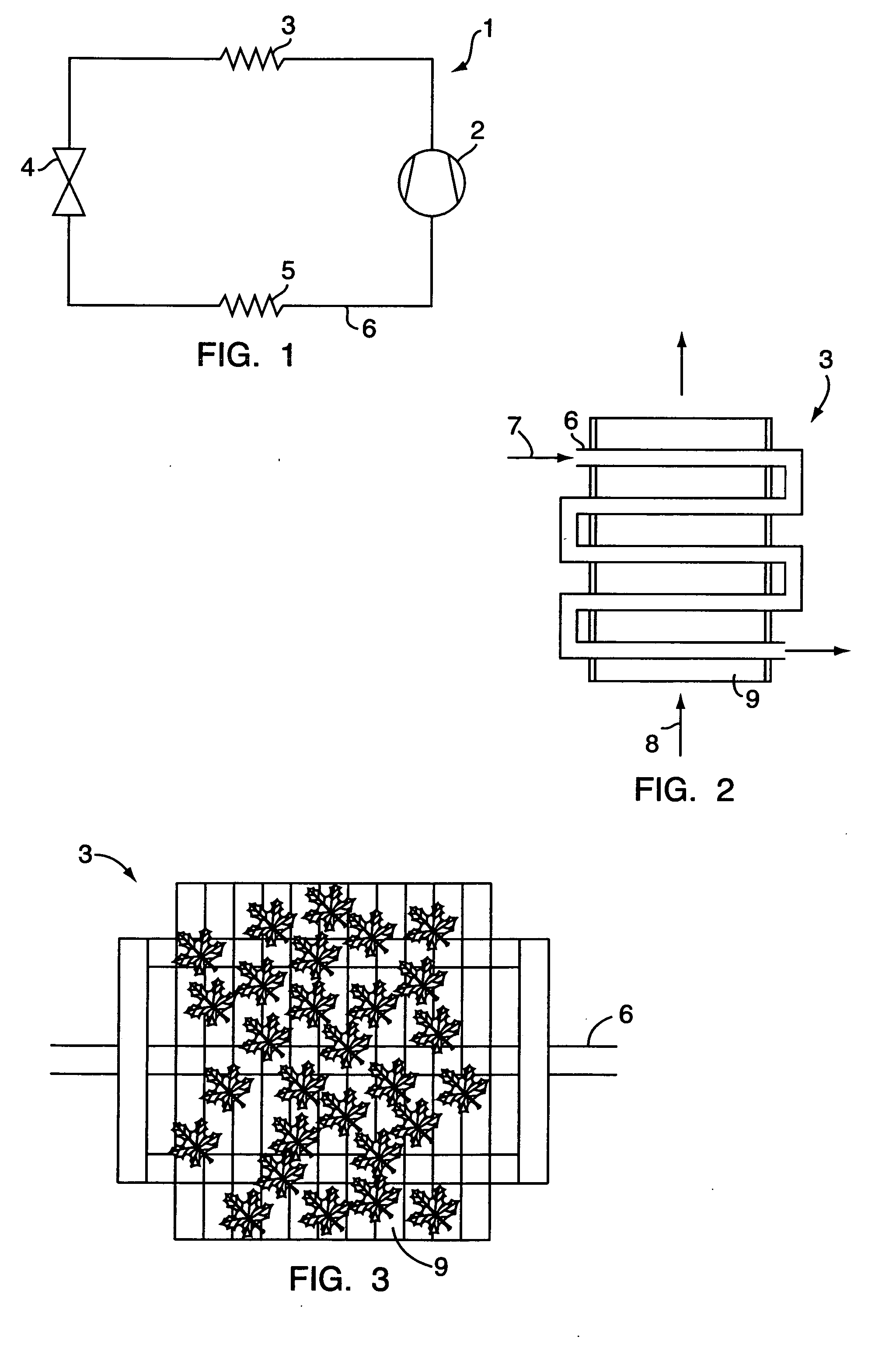
[0040] In FIG. 1 is shown a simple refrigeration system 1 comprising a compressor 2, a condenser 3, an expansion device 4 and an evaporator 5, which are connected by a conduit 6 in which a refrigerant is circulating. In vapour-compression refrigeration or heat pump systems the refrigerant circulates in the system and undergoes phase change and pressure change. In the system 1 a refrigerant gas is compressed in the compressor 2 to achieve a high pressure refrigerant gas, the refrigerant gas is fed to the condenser 3 (heat exchanger), where the refrigerant gas is cooled and condensates, so the refrigerant is in liquid state at the exit from the condenser 3, expanding the refrigerant i...


PUM


Abstract

A method and a device for detecting an abnormality of a heat exchanger exchanging heat between a first fluid flow flowing in a conduit and a second fluid flow flowing along a flow path, said conduit and said flow path each having an inlet and an outlet, whereby the method comprises the steps of establishing at least one parameter representative of the temperature conditions of the heat exchanger, establishing a second fluid inlet temperature, establishing a parameter indicative of expected heat exchange between the heat exchanger and the second fluid, processing the heat exchanger temperature, the second fluid temperature and the parameter indicative of expected heat exchange for establishing an estimated second fluid outlet temperature, and employing the estimated second fluid outlet temperature for evaluating the heat exchange between the first and second fluids by comparing the estimated second fluid outlet temperature, or a parameter derived therefrom, with a reference value.

Description

CROSS REFERENCE TO RELATED APPLICATIONS [0001] This application is entitled to the benefit of and incorporates by reference essential subject matter disclosed in international Patent Application No. PCT / DK2003 / 000701 filed on Oct. 14, 2003 and Danish Patent Application No. PA 2002 01582 filed on Oct. 15, 2002.FIELD OF THE INVENTION [0002] The present invention relates to a method and a device for detecting an abnormality of a heat exchanger exchanging heat between a first fluid flow flowing in a conduit and a second fluid flow flowing along a flow path, said conduit and said flow path each having an inlet and an outlet, and the use of such a device. BACKGROUND OF THE INVENTION [0003] Heat exchangers are an important part of many plants and systems, especially refrigeration or heat pump systems. These heat exchangers and their efficiency are of crucial importance in such systems, and it is therefore important to monitor functioning of the heat exchangers to be able to detect abnormal...

Claims


Application Information

Patent Timeline
Patent Type & Authority Applications(United States)
IPC IPC(8): B60H1/00F28F27/00G01M99/00
CPCB60H1/00978B60H1/3227F25B49/005F28F2200/00F28F27/00G01M99/002F28B11/00
Inventor THYBO, CLAUSCHRISTIAN, BENDTSEN
Owner DANFOSS AS
Why Eureka
Try Eureka