Sealing structure

a hermetically sealed, casing technology, applied in the direction of hermetically sealed casings, semiconductor/solid-state device details, coupling device connections, etc., can solve the problems of poor design flexibility in a few cases, difficult to select optimal materials, and poor shape of the constituent member of the flat cable. , to achieve the effect of simple hermetically sealed structure, easy to form seals, and flexible material selection

Inactive Publication Date: 2006-02-16
NOK CORP
View PDF2 Cites 30 Cited by
  • Summary
  • Abstract
  • Description
  • Claims
  • Application Information

AI Technical Summary

Benefits of technology

[0032] According to the structures of the invention, the seal can be formed without heating or pressurizing. Thus, the conditions of the endurable temperature and endurable pressure are not strict. Therefore, the flexibility of selection of materials for various constituent members, especially constituent members of the flat cable is high. The liquid rubber material is disposed in a desired location, and if the rubber material is subjected to the physical action for example, the seal can be formed. Therefore, it is easy to form the seal and the hermetic structure is simple.

Problems solved by technology

For example, there is a case in which it is difficult to select an optimal material.
The flexibility of design concerning a shape of the constituent member of the flat cable and a shape of the seal material is poor in some cases.
For example, there is a case in which it is difficult to select an optimal material.
The flexibility of design concerning a shape of the constituent member of the flat cable and a shape of the resin material is poor in some cases.
However, the waterproof connector has a drawback that a structure of a waterproof seal itself is complicated.
Thus, there is a drawback that a thickness and a width of the flat cable which originally have high design flexibility are limited.
If a structure in which the flat cable is fixed using a resin material or hard rubber material is employed, the following problem is generated.
Therefore, there is an adverse possibility that the flat cable is folded, cut, peeled off or deviated.
Thus, the bending angle or the bending times of the flat cable are limited.
However, if the grommet is used for the flat cable, the following problem is generated.
With this, costs are also increased.

Method used


Image

  • Sealing structure
  • Sealing structure
  • Sealing structure

Examples


first embodiment

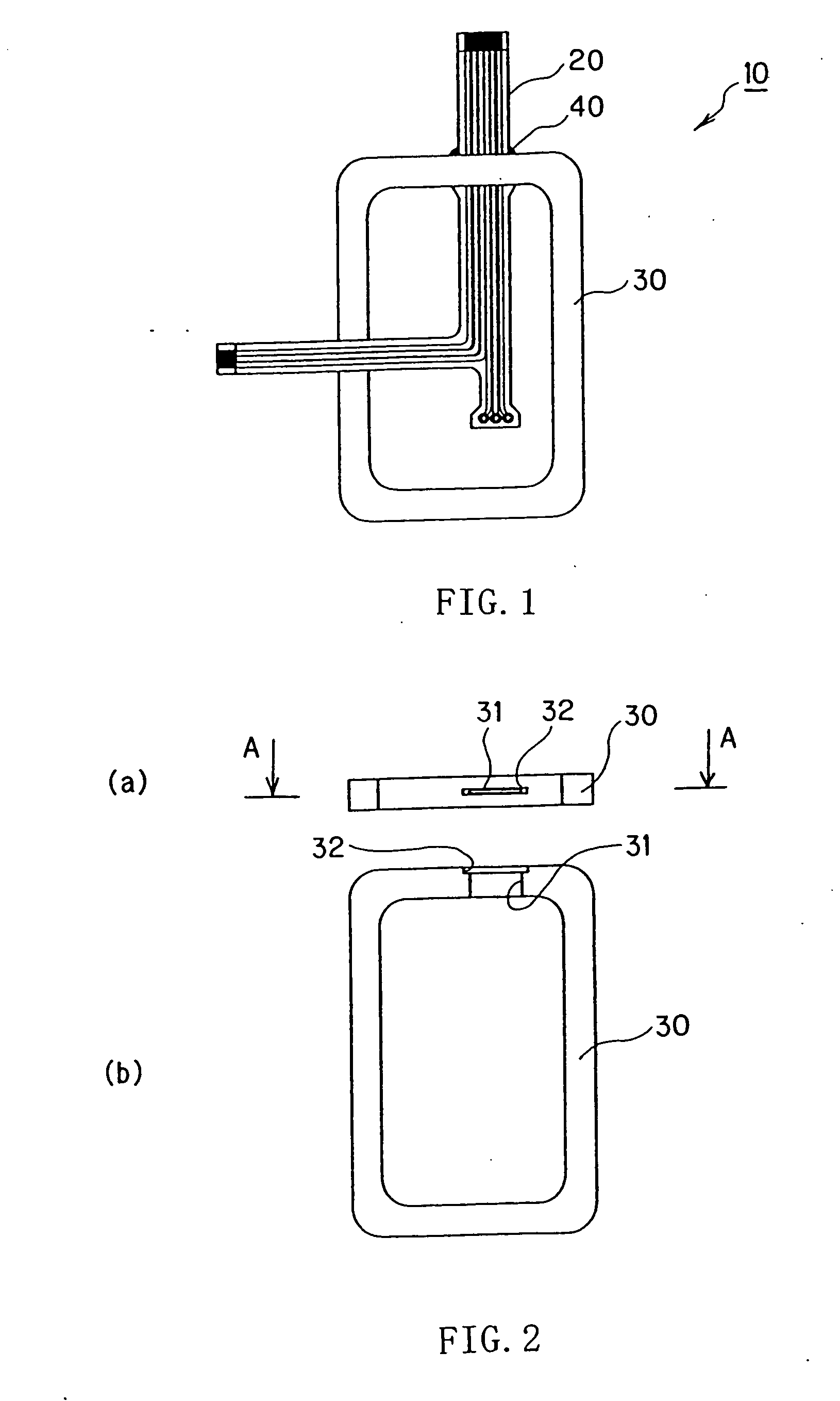
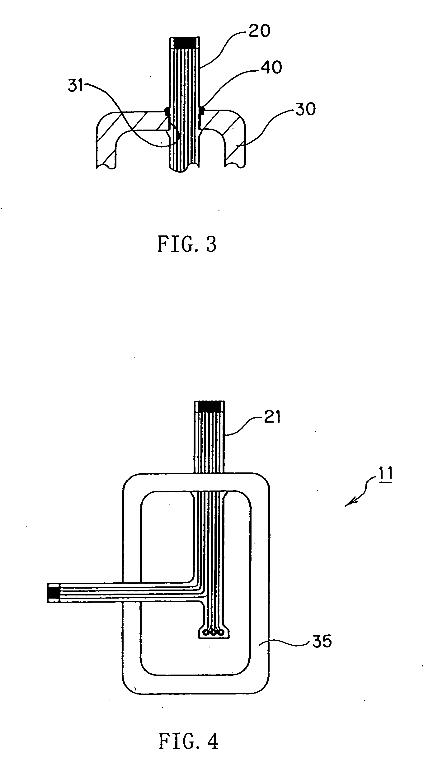
[0042] A hermetic structure according to a first embodiment of the invention will be explained with reference to FIGS. 1 to 3. FIG. 1 is a plan view showing the hermetic structure of the first embodiment of the invention. FIG. 2 show an outer appearance of a seal member constituting the hermetic structure of the first embodiment of the invention, wherein FIG. 2(a) is a front view and FIG. 2(b) is a plan view thereof. FIG. 3 is a portion of a sectional view of the hermetic structure of the first embodiment of the invention (a portion of sectional view taken along a line A-A in FIG. 2 in which a flat cable is inserted).

[0043] As shown in FIG. 1, a hermetic structure 10 of the embodiment includes a flat cable 20 such as FPC and FFC, and a seal member 30 for sealing a desired gap (not shown).

[0044] As shown in FIG. 2, the seal member 30 includes an insertion hole 31 into which the flat cable 20 is inserted, and an introducing groove 32 into which a liquid rubber is introduced.

[0045] ...

second embodiment

[0057] FIGS. 4 to 6 show a second embodiment of the invention. In the first embodiment, liquid rubber which is cured by the physical action is used as a material of the seal which seals the gap between the insertion hole provided in the seal member and the flat cable inserted into the insertion hole. In the second embodiment, a liquid rubber which is cured by the physical action is used as a material of a seal which integrally forms the flat cable.

[0058]FIG. 4 is a plan view of the hermetic structure of the second embodiment of the invention. FIGS. 5 and 6 show an outer appearance of forming dies which produces the constituent member of the hermetic structure of the second embodiment of the invention. FIG. 5(a) is a plan view showing an inner side of one of the forming dies, and FIG. 5(b) is a sectional view taken along a line B-B in FIG. 5(a). FIG. 6(a) is a plan view of an inner side of the other forming die, and FIG. 6(b) is a sectional view taken along a line C-C in FIG. 6(a). ...

third embodiment

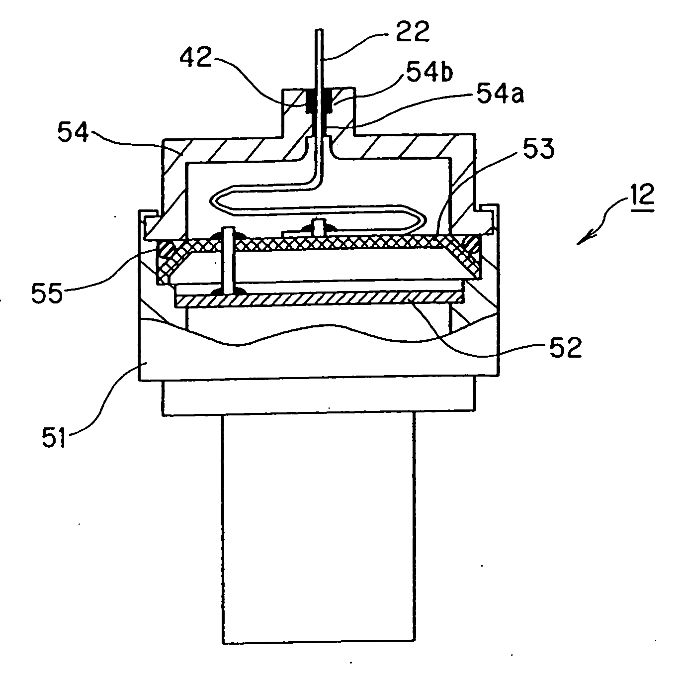
[0072]FIG. 7 shows a third embodiment of the invention. In the previous embodiments, the hermetic structures where the flat cable is pulled out from the rubber seal have been explained. In the third embodiment, a hermetic structure where the flat cable is pulled out directly from a housing case or the like of the apparatus body is explained.

[0073] In this embodiment, a pressure sensor as the apparatus is explained. FIG. 7 is a partially cut-away sectional view of the hermetic structure of the third embodiment of the invention. In FIG. 7, a portion of the pressure sensor is cut away so that the hermetic structure can be easily seen.

[0074] The pressure sensor 12 includes a circuit substrate 52 and a plate 53 in a body 51. One end of the flat cable 22 is fixed to the plate 53 by soldering. The circuit substrate 52 and the flat cable 22 are electrically connected to each other through wiring or the like.

[0075] A cap 54 is mounted on an upper portion of the body 51. The flat cable 22 ...


PUM


Abstract

The present invention relates to a hermetic structure having a flat cable. Liquid rubber is charged into a gap to be sealed, the charged liquid rubber is subjected to a physical action at the normal temperature and under the normal pressure, and the liquid rubber is cured to form a seal. By forming the seal in this manner, the limitation of heat resistance and pressure resistance is moderated, the flexibility of selection of materials for various constituent members is enhanced, and the structure is simplified.

Description

TECHNICAL FIELD [0001] The present invention relates to a hermetic structure having a flat cable. BACKGROUND TECHNIQUE [0002] Flat cables are used for apparatuses such as electrical apparatuses, electronics, actuators, sensors and controllers. In such an apparatus, the flat cable must be disposed over two regions (e.g., a region in the apparatus and a region outside the apparatus) in some cases. Examples of the flat cables are flexible printed circuit substrates (referred to as FPC, hereinafter) and flexible flat cables (referred to as FFC, hereinafter). [0003] In this case, in order to isolate the two regions from each other, a location where the flat cable is disposed must be hermetically closed or sealed. The location is generally hermetically closed in the following manners: [0004] (1) A flat cable is integrally formed on a dedicated seal. [0005] (2) A flat cable is integrally formed on a resin housing or case. [0006] (3) A waterproof connector dedicated to a flat cable is used....

Claims


Application Information

Patent Timeline
Patent Type & Authority Applications(United States)
IPC IPC(8): H05K5/06H01R13/52H02G3/08H02G3/22
CPCH01R13/5205H01R13/5216H01R12/59H02G3/22H02G3/088F16J15/14H02G3/24
Inventor MINOSHIMA, KENJISENDA, KAZUHISAYOSHIDA, TAMOTSUIKEDA, AKIHIKO
Owner NOK CORP
Why Eureka
Try Eureka