

Coaxial cable
- Summary
- Abstract
- Description
- Claims
- Application Information
AI Technical Summary
Benefits of technology
Problems solved by technology
Method used
Image

Examples
second embodiment
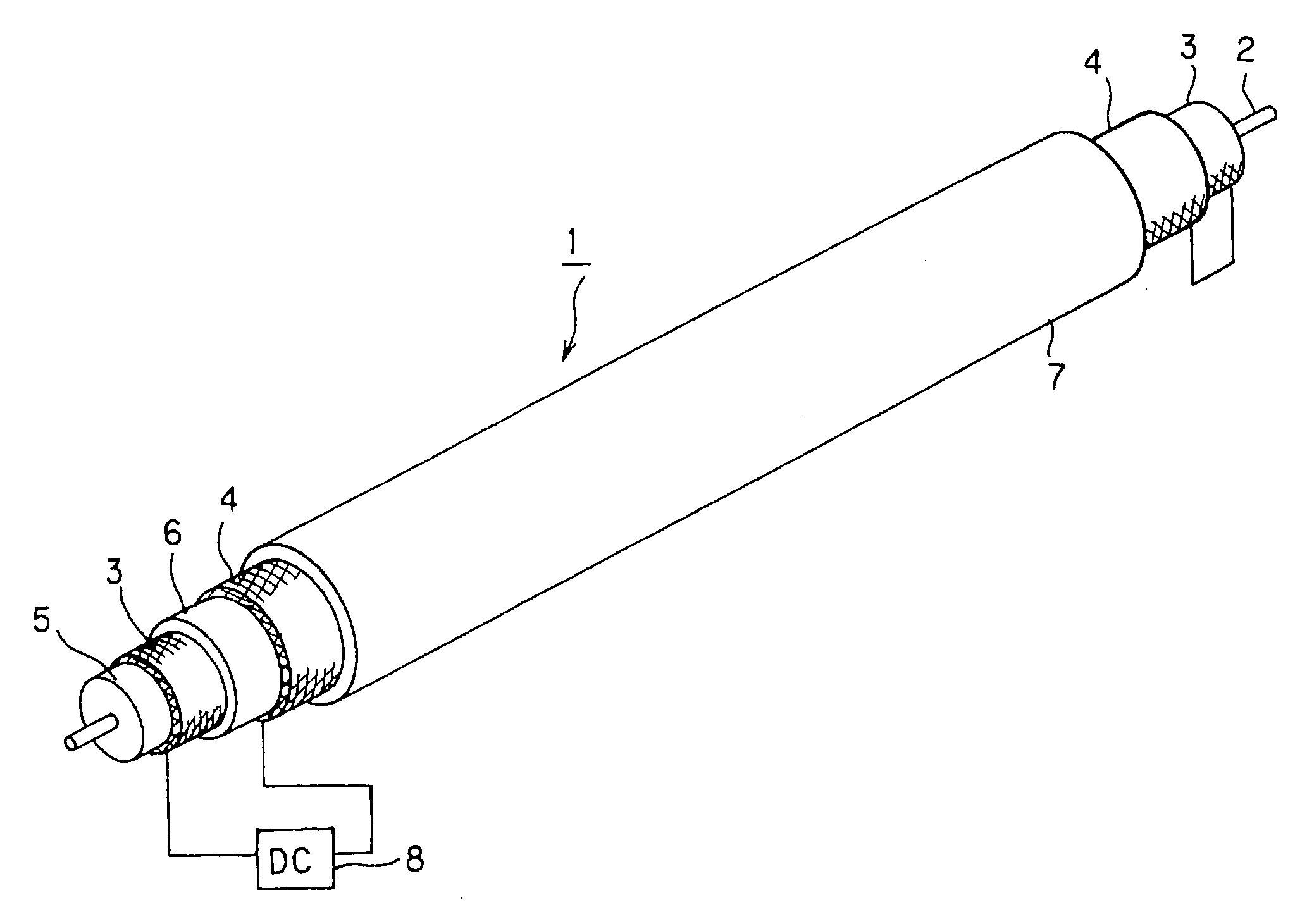
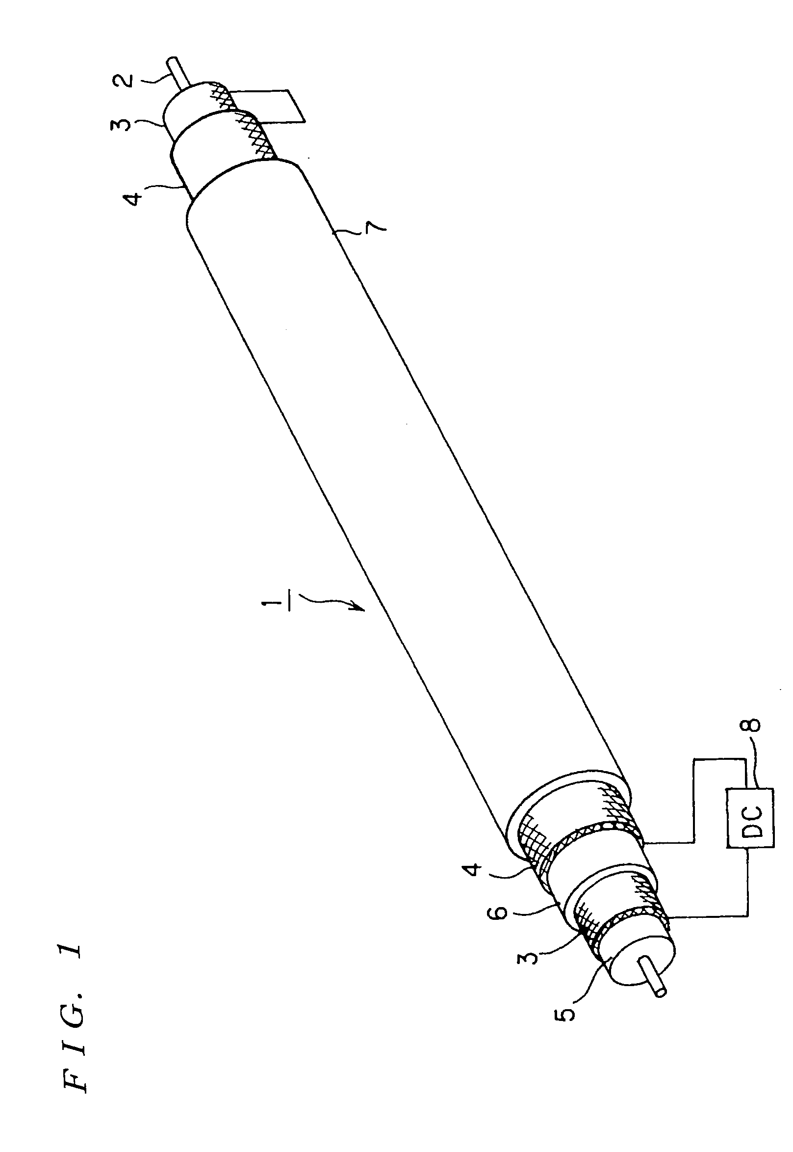
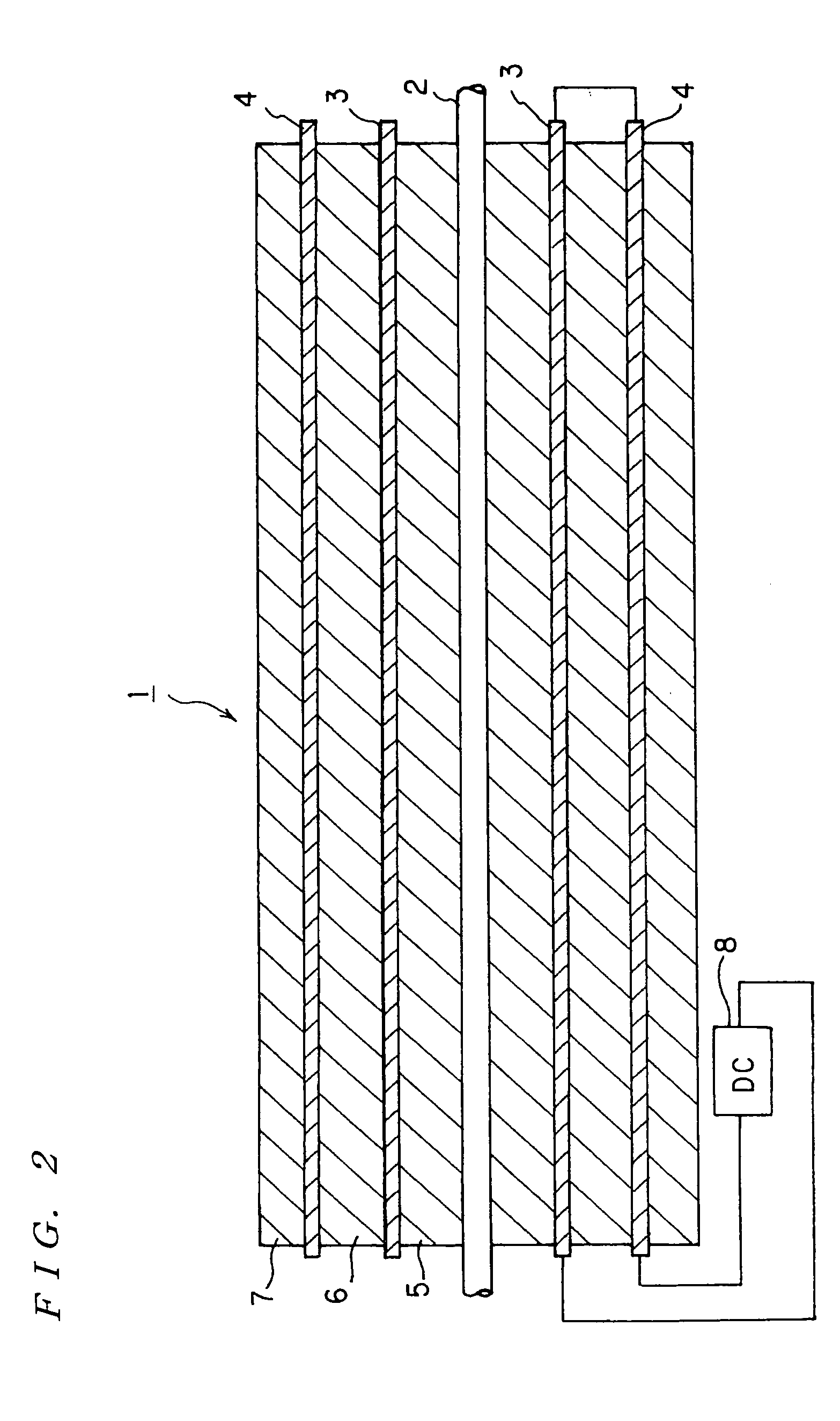
[0036]FIG. 4 is a schematic view of a coaxial cable according to the present invention. In FIG. 4, the numbers as same as those in FIG. 1 are denoted by the same reference numerals and explanations thereof are omitted. As shown in FIG. 4, 31 denotes a first conductor on the outer circumference concentric to the central conductor 2, 41 denotes a second conductor positioned on the outer circumference concentric to the central conductor 2 and outside the first conductor 31, and 8 denotes a DC voltage source which applies a predetermined DC voltage between the first conductor 31 and the second conductor 41 in order to cause direct current having desired current value to flow in the first conductor 31 and the second conductor 41. The first conductor 31 and the second conductor 41 consist of a metal plate cylindrically winded up. The illustrations of a first insulator on the outer circumference of the central conductor 2, a second insulator provided between the first conductor 31 and the ...
third embodiment
[0038]FIG. 5 is a schematic view of a coaxial cable according to the present invention. In FIG. 5, the numbers as same as those in FIG. 1 are denoted by the same reference numerals and explanations thereof are omitted. As shown in FIG. 5, 32 denotes a first conductors on the circumference concentric to a central conductor 2, 42 denotes a plurality of second conductors positioned on the outer circumference concentric to the central conductor 2 and outside the first conductor 31, and 8 denotes a DC voltage source which applies a predetermined DC voltage between the first conductors 32 and the second conductors 42 in order to cause direct current having a desired current value to flow in the first conductors 32 and the second conductors 42. The first conductor 32 and the second conductor 42 consist of plurality of parallel metal conductors electrically connected in respect of both side. The illustrations of a first insulator on the outer circumference of the central conductor 2, a seco...
fourth embodiment
[0040]FIG. 6 is a schematic view of a coaxial cable according to the present invention. In FIG. 6, the numbers as same as those in FIG. 1 are denoted by the same reference numerals and explanations thereof are omitted. A first conductor which is winded around the outer circumference concentric to a central conductor 2 is denoted by 33, 43 denotes a second conductor winded around the outer circumference concentric to the central conductor 2 and outside the first conductor 33, and 8 denotes a DC voltage source which applies DC voltage between the first conductor 33 and the second conductor 43 in order to cause direct current having a desired current value to flow in the first conductor 33 and the second conductor 43. The first conductor 33 and the second conductor 43 consist of metal conductors winded spirally. The illustrations of a first insulator on the outer circumference of the central conductor 2, a second insulator provided between the first conductor 33 and the second conducto...
PUM
 Abstract
Description
Claims
Application Information