Motor/encoder assembly for tape drives

a technology of encoder and tape drive, which is applied in the direction of controlling/driving circuit, driving by direct/indirect member action, mechanical energy handling, etc., can solve the problems of space required to accommodate two separate parts, the size of the components used to create the tape drive also decreases, and achieves compact design

Inactive Publication Date: 2006-02-16
QUANTUM CORP
View PDF18 Cites 14 Cited by
  • Summary
  • Abstract
  • Description
  • Claims
  • Application Information

AI Technical Summary

Benefits of technology

[0008] These and other needs are met by embodiments of the present invention which provide a tape drive comprising a rotor compartment, and means housed within the rotor compartment for coupling a rotor to a tape cartridge, rotating a tape cartridge reel, and encoding a position of the rotor. In certain embodiments of the invention, a magnetic code wheel is attached to the rotor that is rotatably mounted within the motor compartment. A magnetic code wheel sensor is stationarily positioned within the rotor compartment, which senses rotation of the magnetic code wheel. The invention thus improves upon the current limited resolution offered by devices which employ a toothed ring gear and inductive pick-up. Since all three functions are housed within a single rotor (or motor) compartment, a compact design can be provided.

Problems solved by technology

As the form-factor requirement of single reel cartridge tape drives decreases, the size of the components used to create the tape drive also diminish.
The problem with this type of design is the space required to accommodate two separate parts; the motor and the encoder.
In a tape drive system with a form-factor requirement, there is no space available for two separate motor and encoder components.
Furthermore, providing two separate components normally have a higher cost in comparison to provision of a single component having dual functionality.
It also adds assembly time and added cost of inventory.
One problem with such an encoder is its relatively limited resolution.
This is because the size of the tooth is limited in how small the tooth can be made.

Method used


Image

  • Motor/encoder assembly for tape drives
  • Motor/encoder assembly for tape drives
  • Motor/encoder assembly for tape drives

Examples


Embodiment Construction

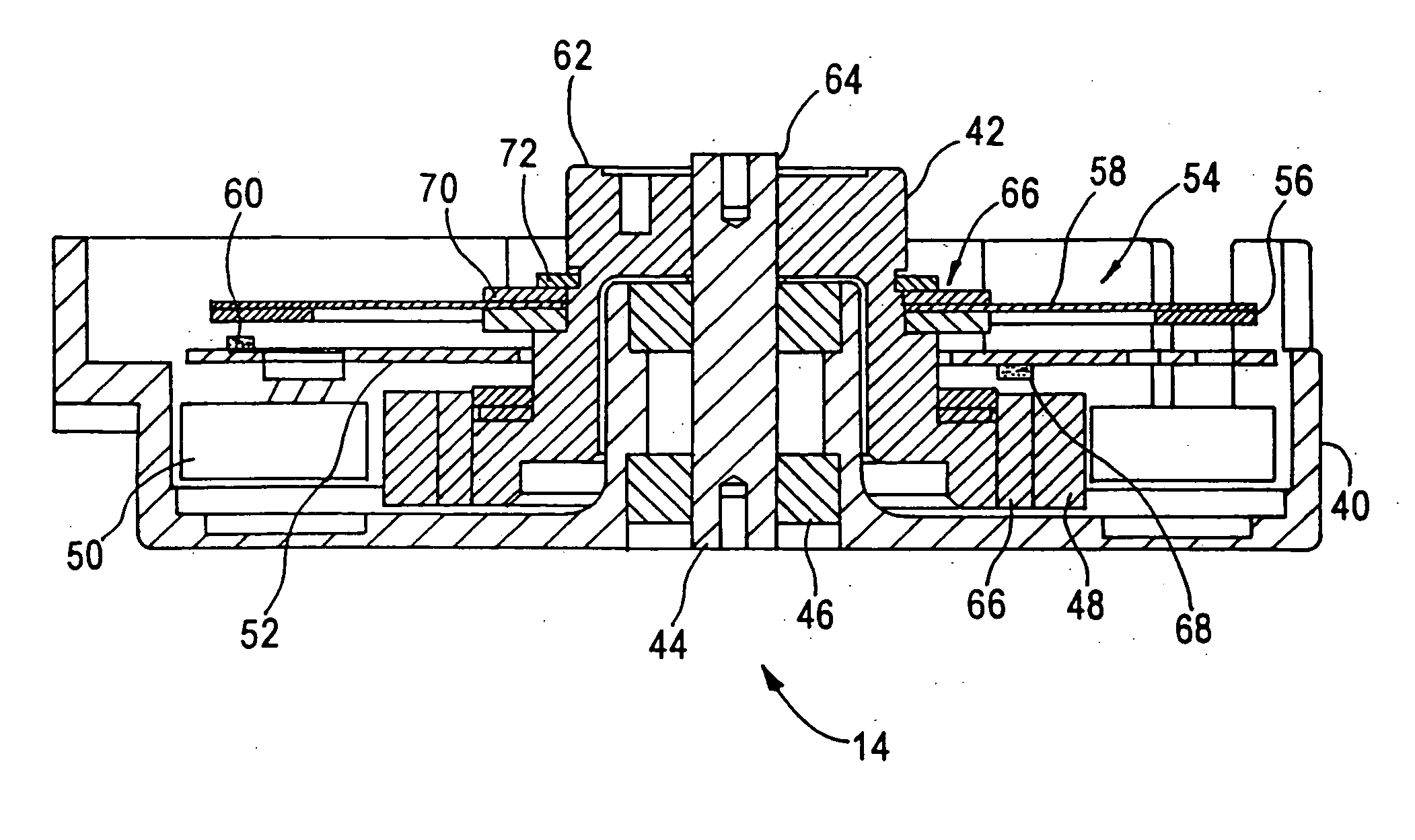
[0021] The present invention addresses and solves problems related to providing motor, encoding and cartridge locating features within a tape drive in a particularly compact manner. These and other problems are solved, in part, by the present invention which provides a DC brushless motor with an inner magnetic rotor. The motor windings and the necessary computation electronics are mounted toward the bottom side of a printed circuit board. The rotor of the motor is extended above the surface of the printed circuit board. The extended rotor provides a precision seat for a magnetic code wheel with multiple poles. The top surface of the printed circuit board provides a mounting surface for the necessary sensors for the encoder. The extension of the rotor provides a precision mounting surface for a cartridge driving chuck. The present invention thus provides a motor, encoder and cartridge coupling device all to be housed in a single rotor (motor) compartment.

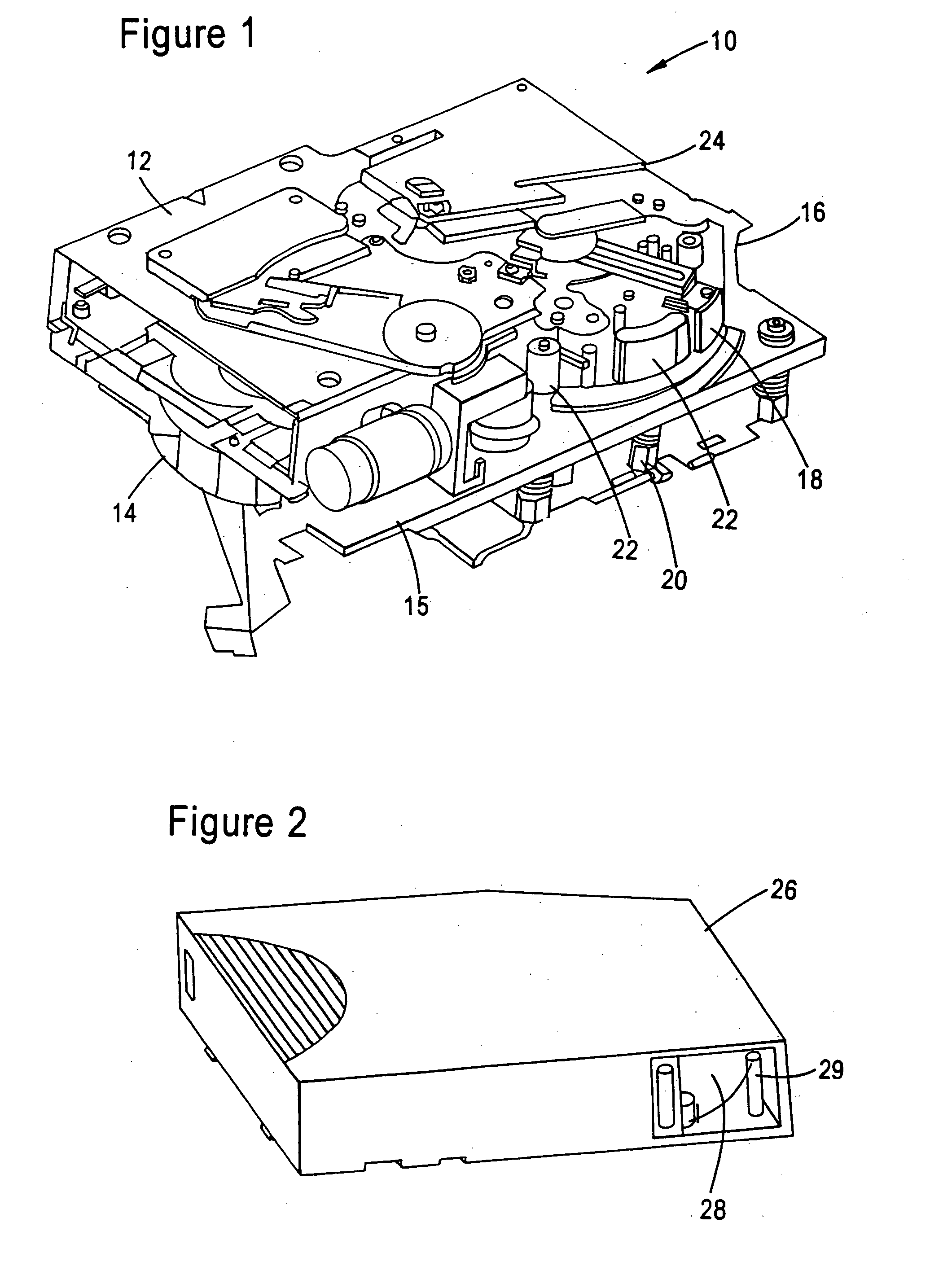
[0022]FIG. 1 is a perspectiv...


PUM


Abstract

A magnetic/encoder assembly has a compact design and combines the features of motor, encoder and chuck locating feature within a single motor housing. The motor/encoder includes a DC brushless motor with an inner magnetic rotor. The motor windings and the commutation electronics are mounted towards the bottom side of a printed circuit board. The rotor of the motor is extended above the surface of the printed circuit board. The extended rotor provides a precision seat for the magnetic wheel with multiple poles. The top surface of the printed circuit board mounts the sensor for the encoder. The extension of the rotor provides the precision mounting surface of the cartridge driving chuck.

Description

FIELD OF THE INVENTION [0001] The present invention relates to the field of tape drives, and more particularly, to a motor / encoder system for a magnetic tape drive. BACKGROUND OF THE INVENTION [0002] In tape drive systems that utilize a single tape cartridge reel, once the cartridge is loaded and is registered at the appropriate datum, the tooth ring coupling of the cartridge reel becomes engaged with the motor system of the tape drive. The lead end of the tape, which is called the leader block or leader pin, is then transferred from the cartridge reel to the take up reel located inside the tape drive. This take up reel is also attached to a motor system. Once a leader pin has been successfully moved to the take up reel, the tape is located against the magnetic head of the tape drive and both of the reels of the tape drive are ready to be rotated by the motor / encoder, to start the read / write process. [0003] The motor / encoder system of a tape drive may have a number of functions, dep...

Claims


Application Information

Patent Timeline
Patent Type & Authority Applications(United States)
IPC IPC(8): H02K7/00H02K11/00
CPCG11B15/26H02K7/14H02K29/10H02K11/0073H02K29/08H02K11/0021H02K11/215H02K11/33
Inventor NAYAK, ASHOK B.HEINZE, ROBERT R.
Owner QUANTUM CORP
Why Eureka
Try Eureka