Magnetometer having an electromechanical resonator

a technology of electromechanical resonators and magnetometers, applied in the field of magnetometers, can solve the problems of excessive heating and/or unacceptably high power consumption, strong micro-magnets, and relatively difficult processing and integration, and achieve the effect of dampening the oscillation of deformable beams

Inactive Publication Date: 2006-02-16
LUCENT TECH INC
View PDF5 Cites 8 Cited by
  • Summary
  • Abstract
  • Description
  • Claims
  • Application Information

AI Technical Summary

Problems solved by technology

One problem with prior-art miniature magnetometers is that they typically include strong micro-magnets, either permanent or electric.
Permanent micro-magnets require magnetic (e.g., ferromagnetic and / or magnetostrictive) materials that are relatively difficult to process and integrate into the magnetometer structure with conventional micro-fabrication techniques.
Micro-electromagnets, while relatively easy to manufacture, require passage of electrical current, which may cause excessive heating and / or unacceptably high power consumption.

Method used


Image

  • Magnetometer having an electromechanical resonator
  • Magnetometer having an electromechanical resonator
  • Magnetometer having an electromechanical resonator

Examples


example 1

A. Example 1

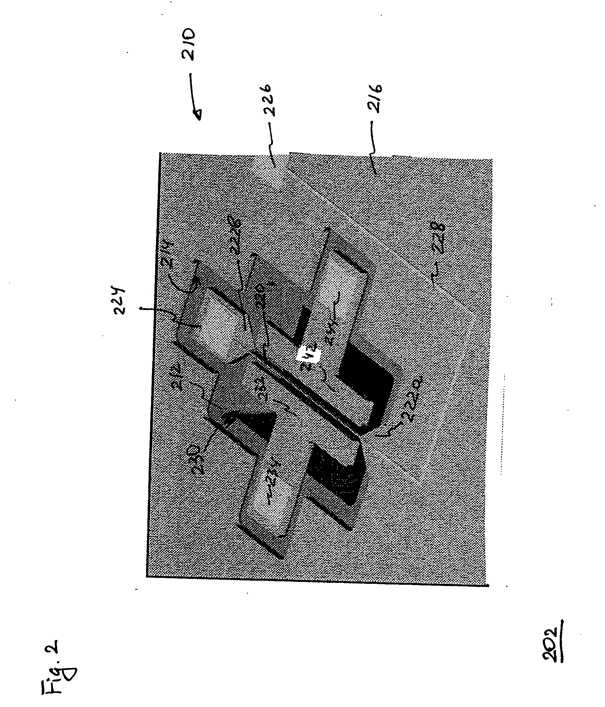
[0069] Suppose that one wants to monitor variations in the Earth's magnetic field (which has a strength of about 0.5 gauss) and, based on fabrication, vacuum, vibration, and / or electronics issues, requires a relatively high value for f1, e.g., f1=20 kHz. Then, resonator 202 satisfies this requirement when beam 220 is implemented, e.g., using the following parameters: w=1 μm; l=620 μm; h=7.75 μm. Using the conductivity of doped silicon (i.e., the material of beam 220), one finds that the beam has a resistance of about 800 Ohm. If this resistance is the load resistance (e.g., contact pads 224 and 226 are simply connected by a well-conducting wire) and Qint=105 then BQ=1670 gauss. Alternatively, when beam 220 is covered by a film of gold that is about 0.6 μm thick, then Rload≈Rgold≈26 Ohm and BQ=300 gauss. Selecting gd=gD=15.5 μm and using Eq. (46), one also finds that the maximum bias voltage for bias generator 312 is about 120 V.

[0070]FIG. 5 graphically shows resonant fr...

example 2

B. Example 2

[0072] The region of optimum sensitivity for resonator 202 can be shifted toward lower fields by implementing the resonator with a relatively low value of f1, e.g., f1=2 kHz. Resonator 202, in which beam 220 has the following dimensions: w=10 μm; l=6200 μm; and h=77.5 μm, meets this specification. When beam 220 is covered by a film of gold that is about 2 μm thick, Rgold≈7.4 Ohm and BQ=160 gauss.

[0073]FIG. 7 graphically shows magnetometer sensitivity as a function of the magnetic-field strength for resonator 202 that is implemented with the above-indicated parameters of this example. Curves 702 and 704 correspond to a drive signal resulting in ymp / w=0.1, and curves 706 and 708 correspond to a drive signal resulting in ymp / w=1.0. Curves 702 and 706 represent a configuration in which Bbias=0, and curves 704 and 708 represent a configuration in which Bbias=160 gauss. FIG. 7 indicates, for example, that, when the resonator is driven with ymp=w=1.0 in an external magnetic fi...


PUM


Abstract

In one embodiment, a magnetometer includes an electromechanical resonator coupled to a drive-and-detect (DD) circuit. The resonator has a deformable beam that is a part of a closed current path. By applying a periodic drive signal to a drive electrode located in proximity to the deformable beam, the DD circuit induces an oscillation of the beam. In the presence of a magnetic field, this oscillation changes the magnetic flux through the closed current path, thereby generating an oscillating electrical current in the path. Dissipation of this current due to resistive losses in the closed current path then dampens the oscillation of the deformable beam with a damping coefficient that depends on the magnetic-field strength. Using a sense electrode located in proximity to the deformable beam, the DD circuit detects the oscillation amplitude. Based on the detected amplitude, the DD circuit changes the frequency of the drive signal to find the resonant frequency. Since the resonant frequency depends on the damping coefficient, the magnetic-field strength can be deduced in a relatively straightforward manner from the resonant frequency.

Description

BACKGROUND OF THE INVENTION [0001] 1. Field of the Invention [0002] The present invention relates to magnetometers and, more specifically, to magnetometers based on electromechanical resonators. The present invention also relates to micro-electromechanical systems (MEMS). [0003] 2. Description of the Related Art [0004] Magnetometers are widely used in a variety of applications, such as extraterrestrial exploration, industrial process sensors, medical imaging equipment, scientific equipment, and detection of mineral deposits and submerged ships. The current trend in magnetometer design and development is consistently toward smaller size, lower power consumption, and lower cost for a desired set of performance characteristics. Examples of prior-art miniature magnetometers can be found in U.S. Pat. Nos. 5,998,995, 5,731,703, and 5,644,230, the teachings of all of which are incorporated herein by reference. [0005] One problem with prior-art miniature magnetometers is that they typically...

Claims


Application Information

Patent Timeline
Patent Type & Authority Applications(United States)
IPC IPC(8): H03K17/95
CPCG01R33/0283
Inventor GREYWALL, DENNIS S.
Owner LUCENT TECH INC
Why Eureka
Try Eureka