MEMS-based inertial switch

a technology of inertial switch and memory, which is applied in the field of switches, can solve the problems of large size high manufacturing and assembly cost, and prone to mechanical failure of conventional inertial switch, and achieve the effects of small size, low cost and small siz

Active Publication Date: 2006-02-16
LUCENT TECH INC +1
View PDF17 Cites 5 Cited by
  • Summary
  • Abstract
  • Description
  • Claims
  • Application Information

AI Technical Summary

Benefits of technology

[0006] Problems in the prior art are addressed, in accordance with the principles of the present invention, by an inertial switch designed as a MEMS device. In one embodiment, the MEMS device is manufactured using a layered wafer and has a movable electrode supported on a substrate layer of the wafer and a stationary electrode attached to that substrate layer. The movable electrode is adapted to move with respect to the substrate layer in response to an inertial force such that, when the inertial force per unit mass reaches or exceeds a contact threshold value, the movable electrode is brought into contact with the stationary electrode, thereby changing the state of the inertial switch from open to closed. In one implementation, the MEMS device is a substantially planar device, designed such that, when the inertial force is parallel to the device plane, the displacement amplitude of the movable electrode from a zero-force position is substantially the same for all force directions. Advantageously, an inertial switch of the invention is a monolithic device, which enables the switch to have a relatively small size (e.g., about one millimeter) and be relatively inexpensive. Due to the small size and low cost, several inertial switches of the invention may be incorporated into a corresponding switch circuit, thereby providing protection against mechanical failure and / or malfunction of any individual inertial switch in that circuit.

Problems solved by technology

A conventional inertial switch is a relatively complex, mechanical device assembled using several separately manufactured components such as screws, pins, balls, springs, and other elements machined with relatively tight tolerance.
As such, conventional inertial switches are relatively large (e.g., several centimeters) in size and relatively expensive to manufacture and assemble.
In addition, conventional inertial switches are often prone to mechanical failure.

Method used


Image

  • MEMS-based inertial switch
  • MEMS-based inertial switch
  • MEMS-based inertial switch

Examples


Embodiment Construction

[0011] Reference herein to “one embodiment” or “an embodiment” means that a particular feature, structure, or characteristic described in connection with the embodiment can be included in at least one embodiment of the invention. The appearances of the phrase “in one embodiment” in various places in the specification are not necessarily all referring to the same embodiment, nor are separate or alternative embodiments mutually exclusive of other embodiments.

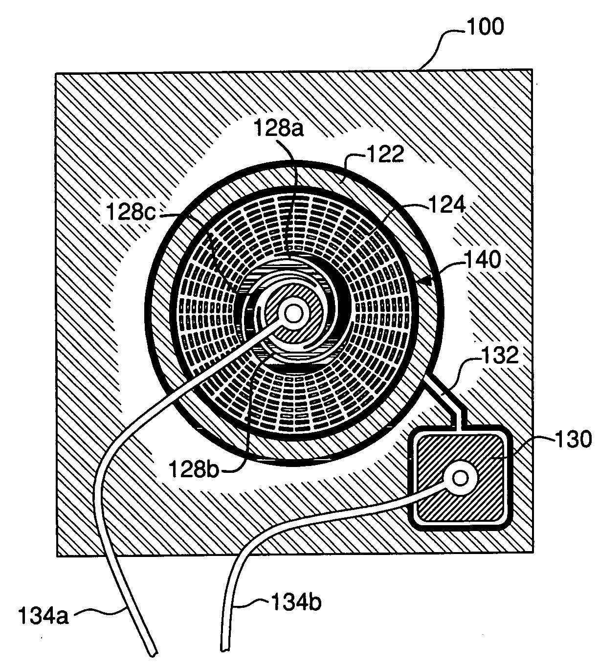
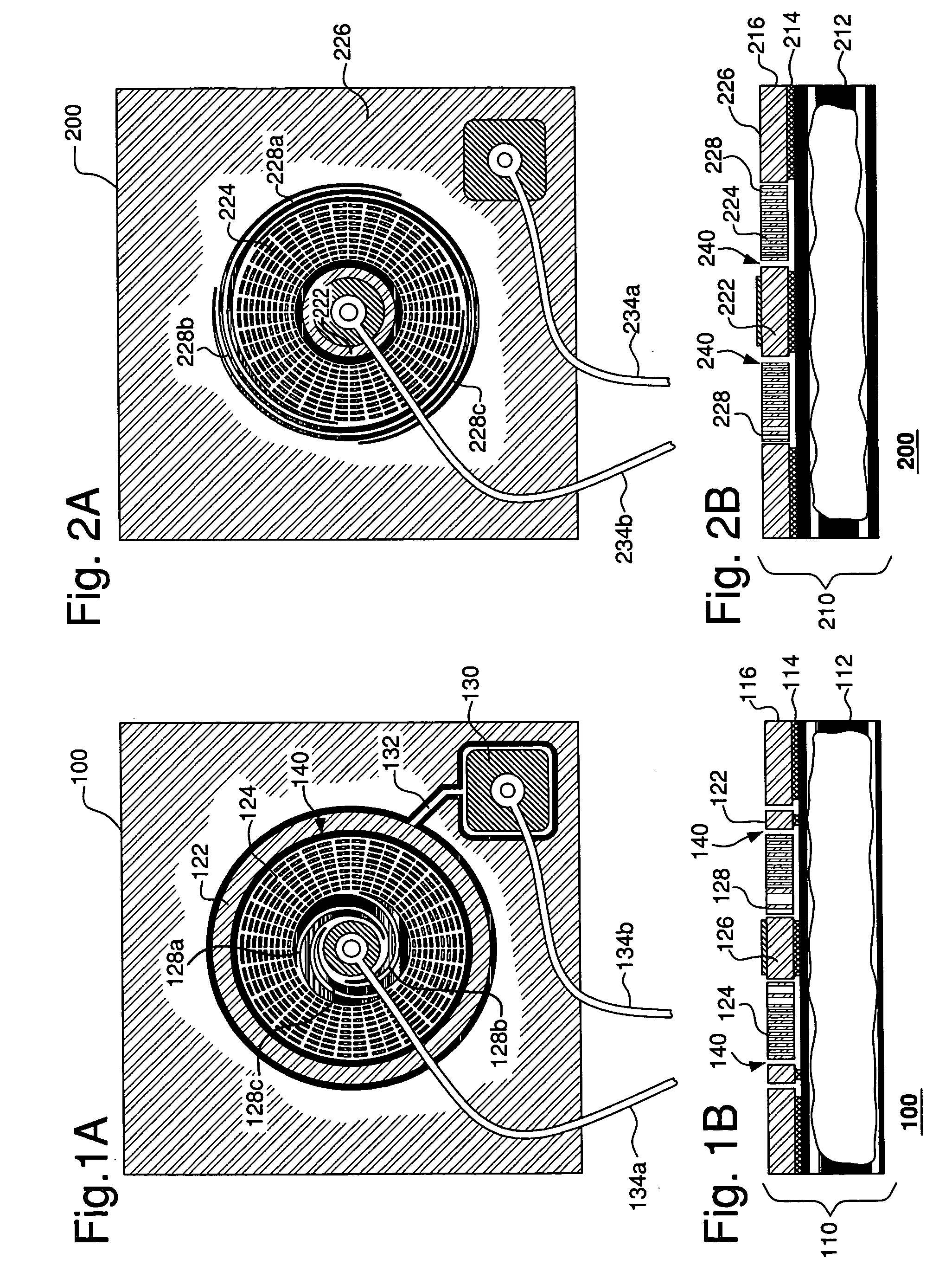
[0012] FIGS. 1A-B show top and cross-sectional views, respectively, of an inertial switch 100 according to one embodiment of the present invention. Switch 100 is a MEMS device manufactured using a silicon-on-insulator (SOI) wafer 110. Since manufacturing techniques for fabricating SOI MEMS structures are well developed, switch 100 can be designed to have a relatively small size. For example, modem lithographic techniques may be used to define various switch elements in wafer 110 with a sub-micron resolution, thereby making it pos...


PUM


Abstract

In one embodiment, an inertial switch of the invention includes a MEMS device manufactured using a layered wafer. The MEMS device has a movable electrode supported on a substrate layer of the wafer and a stationary electrode attached to that substrate layer. The movable electrode is adapted to move with respect to the substrate layer in response to an inertial force such that, when the inertial force per unit mass reaches or exceeds a contact threshold value, the movable electrode is brought into contact with the stationary electrode, thereby changing the state of the inertial switch from open to closed. In one embodiment, the MEMS device is a substantially planar device, designed such that, when the inertial force is parallel to the device plane, the displacement amplitude of the movable electrode from an initial position is substantially the same for all force directions. Advantageously, inertial switches of the invention can be designed to have a relatively small size, e.g., less than one millimeter, and be relatively inexpensive. Due to the small size and low cost, several inertial switches of the invention may be incorporated into a corresponding switch circuit, thereby providing protection against mechanical failure and/or malfunction of any individual inertial switch in that circuit.

Description

BACKGROUND OF THE INVENTION [0001] 1. Field of the Invention [0002] The present invention relates to switches and, more specifically, to motion-sensitive switches. The present invention also relates to micro-electromechanical systems (MEMS). [0003] 2. Description of the Related Art [0004] An inertial switch is a switch that can change its state, e.g., from open to closed, in response to acceleration and / or deceleration. For example, when the absolute value of acceleration along a particular direction exceeds a certain threshold value, the inertial switch changes its state, which change can then be used to trigger an electrical circuit controlled by the inertial switch. Inertial switches are employed in a wide variety of applications such as automobile airbag deployment systems, vibration alarm systems, detonators for artillery projectiles, and motion-activated light-flashing footwear. Description of several representative prior-art inertial switches can be found, for example, in U.S...

Claims


Application Information

Patent Timeline
Patent Type & Authority Applications(United States)
IPC IPC(8): H01H51/22
CPCH01H35/14H01H1/0036
Inventor GREYWALL, DENNIS S.
Owner LUCENT TECH INC
Why Eureka
Try Eureka