Mobile satcom antenna discrimination enhancement

a technology of mobile satcom and antenna discrimination, which is applied in the structure of radiating elements, radio transmission, electrical equipment, etc., can solve the problems of particularly difficult communication with aeronautical satellites, and achieve the effect of low gain, reduced or minimized gain

Inactive Publication Date: 2006-02-16
EMS TECH CANADA
View PDF11 Cites 30 Cited by
  • Summary
  • Abstract
  • Description
  • Claims
  • Application Information

AI Technical Summary

Benefits of technology

[0007] The shape of the radiation pattern of the antenna array is modified dynamically, such that the gain in the direction of other sources is sufficiently low to meet the desired or required spatial discrimination to avoid any significant interference with the other sources. The pattern is controlled by controlling the amplitude and / or the phase of one or more elements within or outside the antenna array. In this manner reduced gain or nulls can be directed at the potentially interfering sources, which are not being utilized by the antenna array for communications. This allows the array to be physically reduced in size, while still satisfying the required spatial discrimination requirements for the array utilization.

Problems solved by technology

When the mobile platform is an aircraft, the communications with the aeronautical satellites is especially challenging, since the aircraft can maneuver quickly and can cover large distances in a short time period.

Method used


Image

  • Mobile satcom antenna discrimination enhancement
  • Mobile satcom antenna discrimination enhancement
  • Mobile satcom antenna discrimination enhancement

Examples


first embodiment

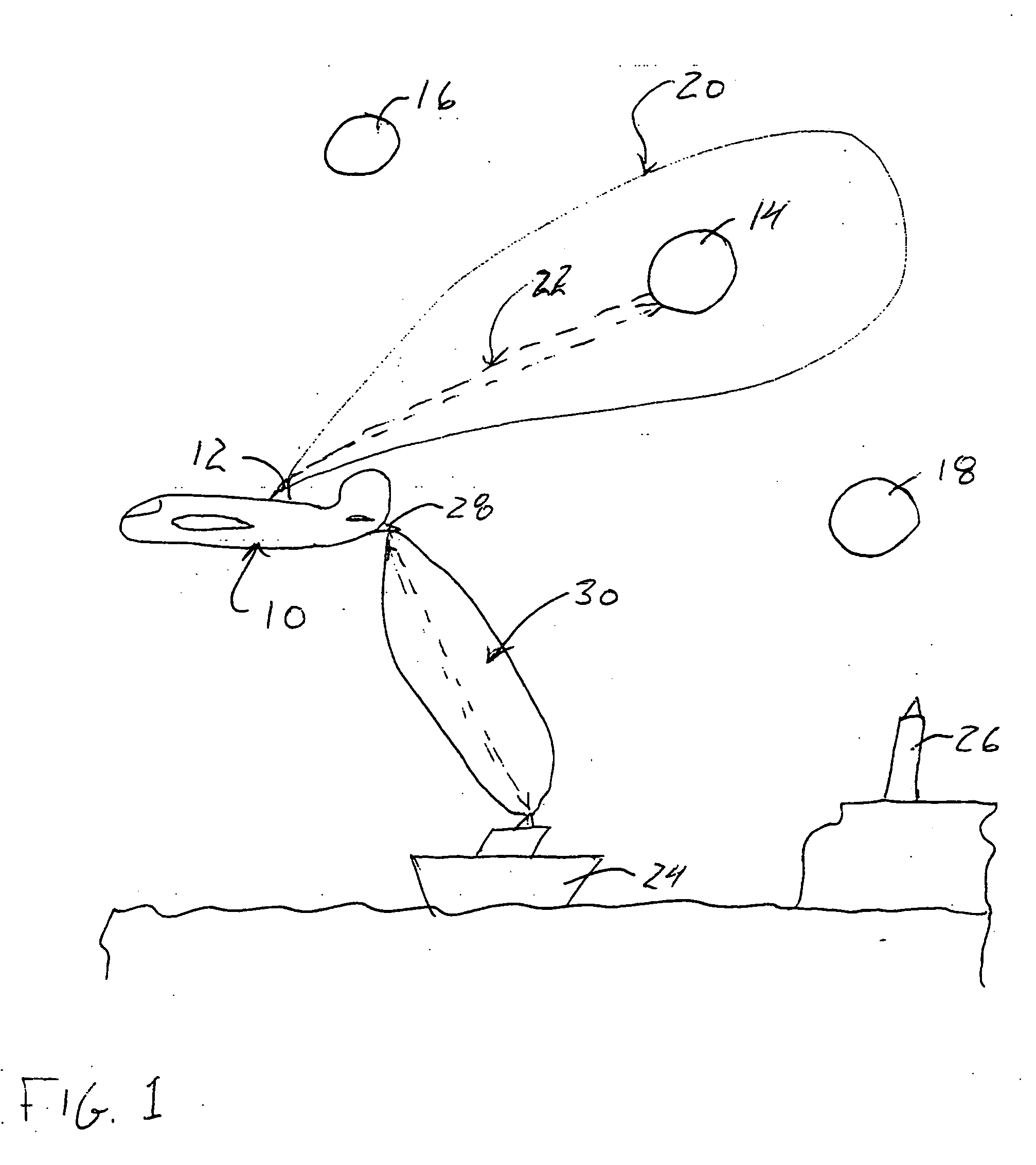
[0027] the antenna array of the present invention is designated generally by the reference numeral 40 in FIG. 2. The array includes four (4) substantially identical antenna elements 42, 44, 46 and 48 forming a regular array grid 50. Although only four antenna elements are illustrated, the grid 50 can include as many as desired or required for the specific application. The antenna elements 42, 44, 46 and 48 are coupled to respective phase shifters, 52, 54, 56 and 58 to control the relative phases of the antenna elements 42, 44, 46 and 48. The antenna elements 42, 44, 46 and 48 then further are coupled to respective attenuators 60, 62, 64 and 66 to control the relative excitation amplitude of each of the antenna elements 42, 44, 46 and 48.

[0028] A common port 68 functions as the RF input to and output from the antenna array 40. The antenna elements 42, 44, 46 and 48 are coupled to the port 68 by respective lines 70, 72, 74 and 76. The antenna elements 42, 44, 46 and 48 are commonly mo...

second embodiment

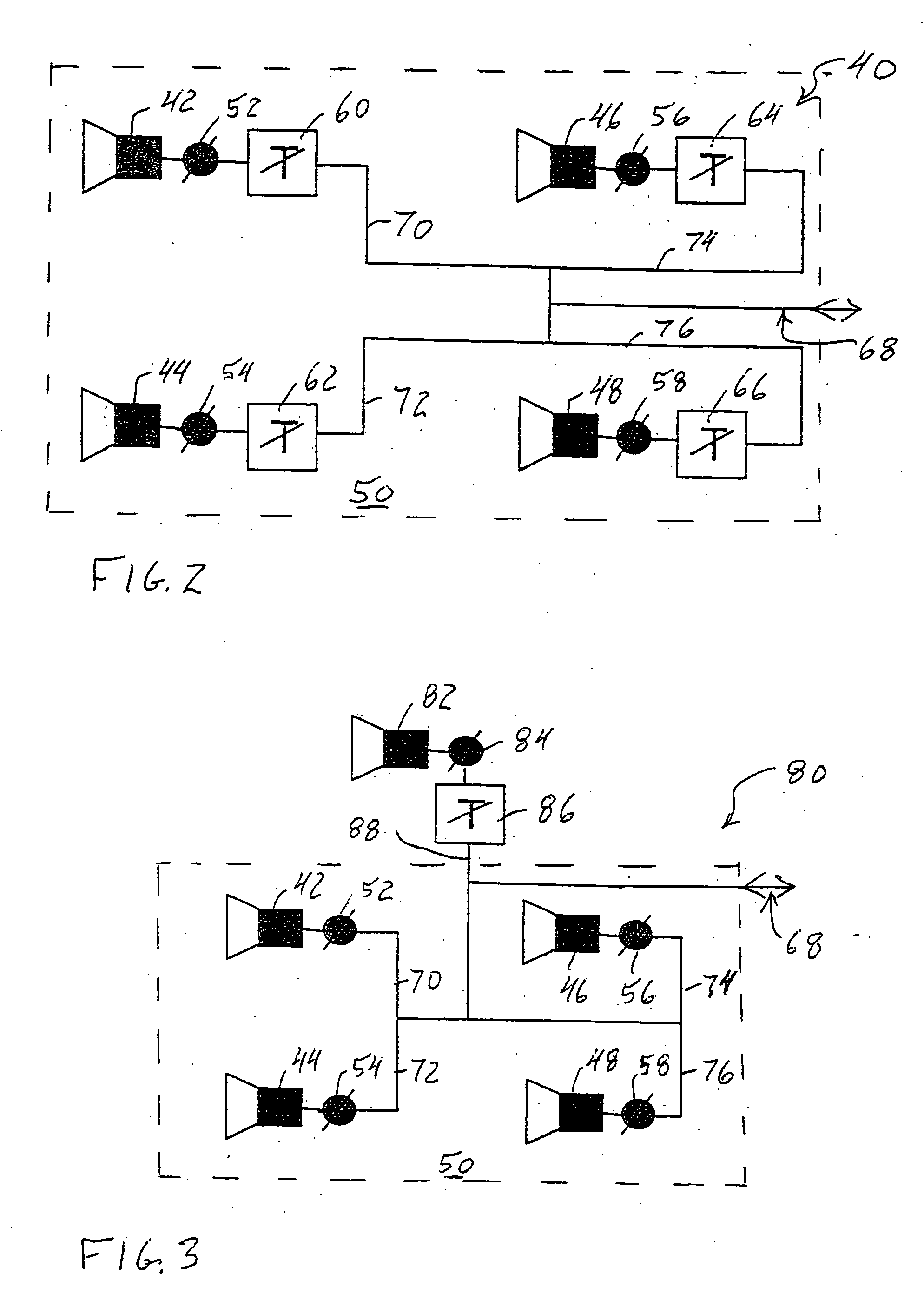
[0029] In the array 40, all of the antenna elements 42, 44, 46 and 48 are located within the commonly-mounted grid 50 formed by the four elements. In contrast, the antenna array of the present invention is designated generally by the reference numeral 80 in FIG. 3. In the array 80, the antenna elements 42, 44, 46 and 48 again are located within the commonly-mounted grid 50 formed by the four elements and again include at least the respective phase shifters 52, 54, 56 and 58. The array 80 also can include the respective attenuators 60, 62, 64 and 66. Additionally, the array 80 includes an additional outrigger antenna element 82, which is typically mounted separately from the main grid of antenna elements. The outrigger antenna element 82 is coupled to a phase shifter 84 and then to an attenuator 86 and then to the common input 68 by a line 88. The outrigger element 82 is excited and controlled to produce the desired spatial discrimination or dynamic directed null for the array 80.

[00...


PUM


Abstract

An antenna array especially for use on mobile platforms, which provides the spatial discrimination in selected directions required for such antennas. The shape of the radiation pattern of the antenna array is modified dynamically, such that the gain in the direction of other sources is sufficiently low to meet the desired or required spatial discrimination to avoid any significant interference with the other sources. The pattern is controlled by controlling the amplitude and / or the phase of one or more elements within or outside the antenna array. In this manner reduced gain or nulls can be directed at the potentially interfering sources, which are not being utilized by the antenna array for communications.

Description

TECHNICAL FIELD [0001] The present invention is directed generally to phased-array antennas and more particularly to mobile platform antenna arrays with enhanced spatial discrimination in selected directions. BACKGROUND OF THE INVENTION [0002] Communications from an antenna array on a mobile platform requires control of the antenna radiation pattern so that communication transmissions to and from the mobile platform do not interfere with communications to and from other sources and other mobile platforms, such as separate communications from another source with another mobile platform, such as a satellite. Generally, the radiation pattern or beam from the mobile platform is directed to a satellite of interest and the beam (pattern) shape of the antenna array is designed and / or directed such that interference with other satellites is sufficiently low. For example, the beam width of the pattern from the mobile platform antenna array can be smaller than the angular spacing between the ...

Claims


Application Information

Patent Timeline
Patent Type & Authority Applications(United States)
IPC IPC(8): H01Q3/22H01Q1/36
CPCH01Q3/2682H01Q3/26H04B7/18508H04B7/18513
Inventor STRICKLAND, PETER C.
Owner EMS TECH CANADA
Why Eureka
Try Eureka