Scan control method and X-ray CT apparatus

a control method and a technology of computed tomography, applied in tomography, instruments, applications, etc., can solve problems such as increasing patient burden

Inactive Publication Date: 2006-02-16
GE MEDICAL SYST GLOBAL TECH CO LLC
View PDF10 Cites 26 Cited by
  • Summary
  • Abstract
  • Description
  • Claims
  • Application Information

AI Technical Summary

Benefits of technology

[0018] In the invention according to each of the respective aspects referred to above, the velocity of a helical scan is controlled following motion of a contrast agent in a subject. It is therefore possible to realize a scan control method for performing the optimum contrast photography by an X-ray CT apparatus, and an X-ray CT apparatus which carries out the optimum contrast photography.
[0019] A helical scan is controlled in such a manner that the position of center of the X-ray detector as viewed in the progress direction of the helical scan is equivalent to the position of a leading end of a contrast agent. Images are reconstructed on the basis of projection data respectively obtained through a first half and a latter half as viewed in the progress direction of the helical scan with respect to the center position of the X-ray detector, and thereby an image corresponding to a difference between the images is obtained. It is therefore possible to realize a scan control method for an X-ray CT apparatus, for imaging only a contrasted part, and an X-ray CT apparatus which brings only a contrasted part into image form.

Problems solved by technology

Therefore, the contrast agent is apt to often use so that a burden on a patient increases.

Method used


Image

  • Scan control method and X-ray CT apparatus
  • Scan control method and X-ray CT apparatus
  • Scan control method and X-ray CT apparatus

Examples


embodiment 1

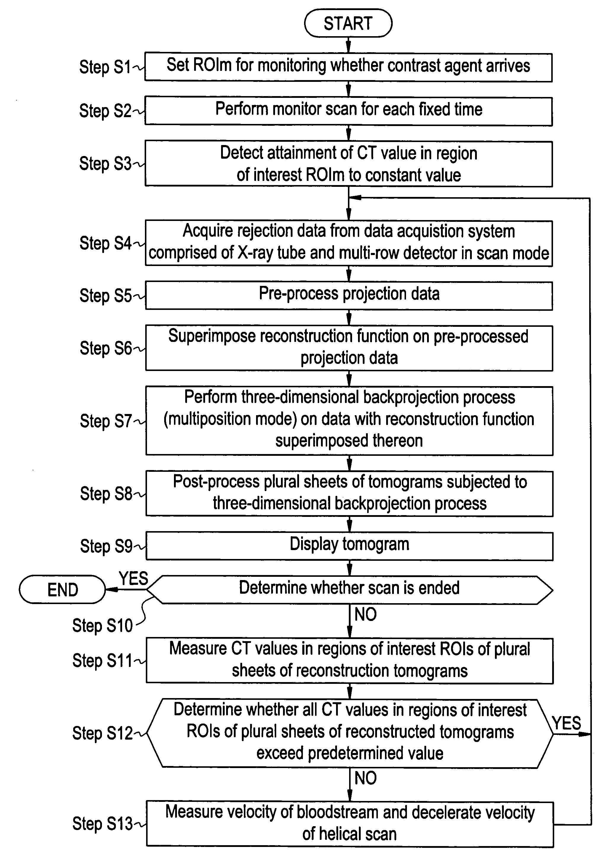
[0058] The operation of the present apparatus will be explained. FIG. 3 is a flow diagram schematically showing the operation of an embodiment 1 illustrative of the X-ray CT apparatus 100.

[0059] In Step S1, a region of interest for monitoring whether a contrast agent arrives, is set. Consequently, such a region of interest ROIm as shown in FIG. 4(b), for example, is set.

[0060] In Step S2, a monitor scan is performed for each fixed time.

[0061] In a monitor phase, the present apparatus performs a conventional scan (axial scan) for each predetermined cycle Δtm as shown in FIG. 4(a) and waits for an average CT value in the region of interest ROIm to reach a constant value or more. It is found that the contrast agent arrives when the average CT value has exceeded a threshold value. The conventional scan at this time may be a single scan or multiscans.

[0062] In Step S3, the attainment of the CT value in the ROI to the constant value is detected.

[0063] In Step S4, projection data are a...

embodiment 2

[0119] Next, FIGS. 29 and 30 show an In this case, the accuracy of tracking of the most leading edge of each bloodstream contrasted in the embodiment is improved, and the center coordinate of a data acquisition system in a z direction is always controlled so as to go to approach the neighborhood of the most leading edge of each contrasted bloodstream.

[0120]FIG. 29 is an explanatory diagram showing an example in which the most leading edge of each contrasted bloodstream is controlled so as to be always placed in the center of the data acquisition system as viewed in the z direction in the embodiment 2. FIG. 30 shows the manner in which only a contrasted bloodstream is extracted from images corresponding to differences, at the same regions and locations, among tomograms of contrasted bloodstreams and tomograms of non-contrasted bloodstreams in the embodiment 2. By performing one variable pitch helical scan in this way, only the contrasted bloodstream is extracted, so that it can be b...


PUM


Abstract

A scan control method for an X-ray CT apparatus wherein a subject with a contrast agent injected therein is helically scanned with an X-ray beam and image reconstruction is performed based on projection data obtained through an X-ray detector. The method includes controlling a velocity of a helical scan following motion of the contrast agent in the subject.

Description

CROSS REFERENCE TO RELATED APPLICATIONS [0001] This Application claims the benefit of Japanese Application No. 2004-235900 filed Aug. 13, 2004. BACKGROUND OF THE INVENTION [0002] The present invention relates to a scan control method and an X-ray CT (Computed Tomography) apparatus, and more specifically to a scan control method for an X-ray CT apparatus, for helically scanning a subject with a contrast agent injected therein, and an X-ray CT apparatus which helically scans a subject with a contrast agent injected therein. Alternatively, the present invention relates to an applied technology for a variable helical scan in an X-ray CT apparatus. [0003] In an X-ray CT apparatus which helically scans a subject with a contrast agent injected therein, a helical scan is performed which is synchronized with the attainment of a bloodstream contrasted with a contrast agent to a region of interest in a monitor phase. In such a case, a scan with a helical scan velocity as constant is carried ou...

Claims


Application Information

Patent Timeline
Patent Type & Authority Applications(United States)
IPC IPC(8): A61B6/00
CPCA61B6/032A61B6/481G01N23/046G01N2223/612A61B6/027A61B6/507G01N2223/419G06T11/005A61B6/03
Inventor NISHIDE, AKIHIKOMORIKAWA, KOTOKOHAGIWARA, AKIRAIMAI, YASUHIRO
Owner GE MEDICAL SYST GLOBAL TECH CO LLC
Why Eureka
Try Eureka