Thermal type air flow meter

a technology of air flow meter and thermoplastic, which is applied in the direction of liquid/fluent solid measurement, instrumentation, testing/calibration of volume flow, etc., can solve the problems of increasing the number of parts of the thermoplastic type air flow meter, increasing production costs, and increasing the stress on the diaphragm section. , to achieve the effect of improving mass productivity, reliability and measurement accuracy

Inactive Publication Date: 2006-02-23
HITACHI LTD
View PDF12 Cites 31 Cited by
  • Summary
  • Abstract
  • Description
  • Claims
  • Application Information

AI Technical Summary

Benefits of technology

[0044] In the above-mentioned example, the diaphragm sections are formed in rectangular shape; however, the present invention is not limited to this constitution. To attain the object, it is important to make identical the maximum stresses exerted on diaphragm sections when the pressure around a sensor element fluctuates. Even in any other shape, the same effect can be produced if there are lengths dependant on the maximum stress and such a construction that these lengths are unified is adopted, as mentioned above.
[0045] If the maximum stresses exerted on the diaphragm sections when the pressure around the sensor element fluctuates are identical, it means the following matter. When an ambient pressure is gradually increased to increase the stress on the diaphragm sections, all the diaphragm sections are broken with substantially the same timing. Therefore, the same effect is also produced if such a shape that diaphragm sections are broken under the same ambient pressure is adopted.
[0046] According to the present invention, a large amount of sensor elements can be screened at a time under optimum pressure. Thus, a thermal type air flow meter that is excellent in mass productivity, reliability, and measurement accuracy can be provided.

Problems solved by technology

The thermal type air flow meter has the following problem: a measuring error is caused due to a change in intake air temperature.
This increases the number of parts of the thermal type air flow meter, and further requires mounting structure and wiring for installing the intake air temperature sensor.
This results in increased production cost.
The pressure in the intake pipe of an engine can be steeply increased due to the occurrence of back fire or the like.
In such a case, a pressure almost two times greater than the atmospheric pressure can be applied to the sensor element of the thermal type air flow meter, and it can be subject to great mechanical stress.
A defective, for example, a sensor element having damage to its diaphragm section, can exist in a manufacturing process.
If such a defective is mounted on an engine and the engine is started, the engine prematurely gets out of order.
This is because the sensor element does not have durability enough to endure the harsh pressure conditions mentioned above.
Therefore, failure in the diaphragm sections of a thermal type air flow meter is one of significant causes of such a premature failure.
The above-mentioned conventional art does not give consideration to problems that may occur when a temperature sensor for measuring the intake air temperature is formed on the sensor element of a thermal type flow meter.
It has trouble with provision of sensor elements free from defect.
As described with respect to the above conventional art, a problem arises when a resistor 11 for intake air temperature sensor is formed on a sensor element 1.
Since the sensor element is as small as several millimeters, it is substantially impossible to adjust the test pressure from one diaphragm section to another diaphragm section.
As a result, satisfactory screening cannot be carried out.
Or, the pressure is insufficient for the other diaphragm section, and satisfactory screening cannot be carried out.
In either case, provision of sensor elements free from defect cannot be expected.

Method used


Image

  • Thermal type air flow meter
  • Thermal type air flow meter
  • Thermal type air flow meter

Examples


first embodiment

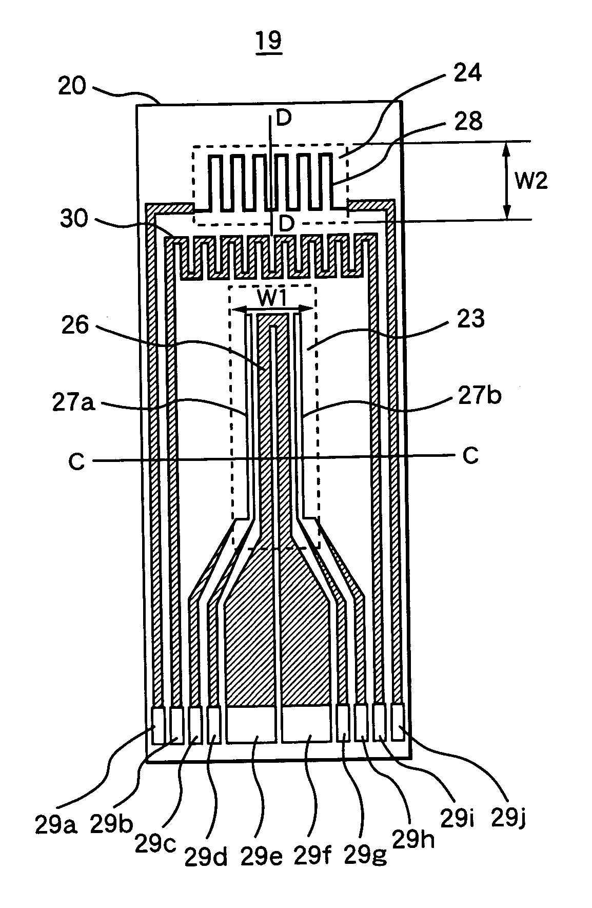
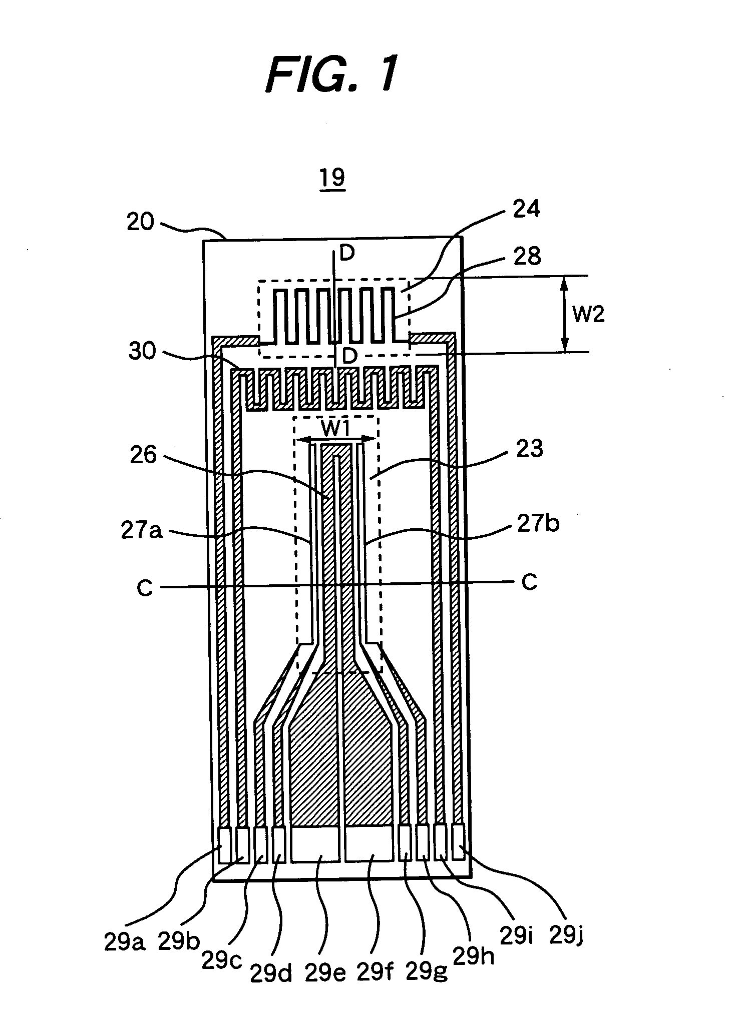
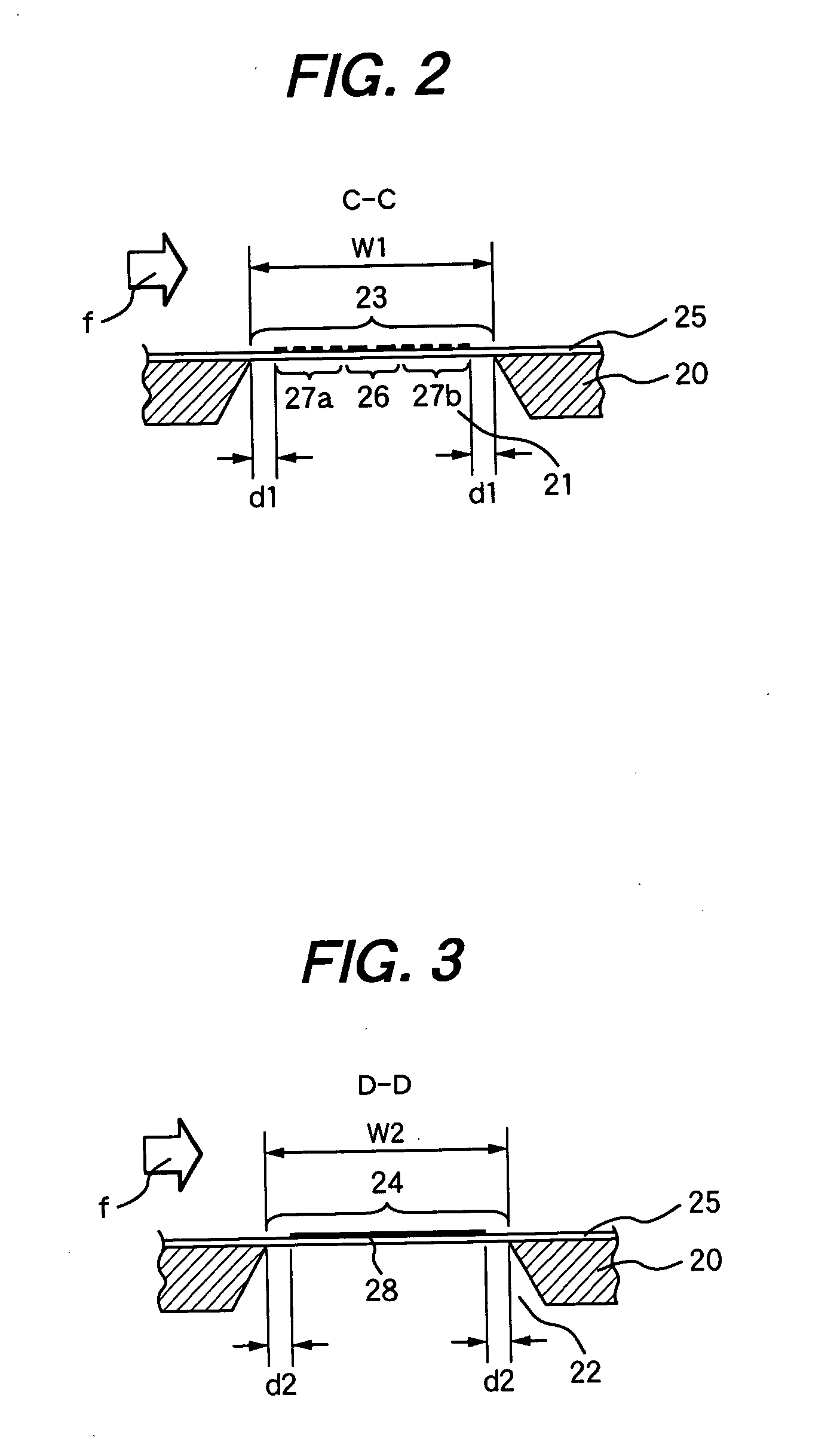
[0070]FIG. 1 is a plan view of a sensor element in a thermal type air flow meter according to the present invention. FIG. 2 is a sectional view taken along the line C-C of FIG. 1, and FIG. 3 is a sectional view taken along the line D-D of the same. In FIG. 1, numeral 19 denotes the sensor element of the thermal type air flow meter.

[0071] In the example illustrated in these drawings, the whole of the sensor element 19 is formed based on a semiconductor substrate 20 comprising a single crystal silicon (Si) plate. A cavity portion 21 and a cavity portion 22 are formed in this semiconductor substrate 20. Both of the cavity portion 21 and the cavity portion 22 are formed as holes whose planar shape is a rectangle.

[0072] In FIGS. 2 and 3, arrow f indicates the direction in which a fluid to be measure (intake air) flows relative to the sensor element 19. In these drawings, therefore, the left side is upstream and the right side is downstream.

[0073] A diaphragm section 23 as a first diaph...

second embodiment

[0115]FIG. 10 is also a schematic plan view of the sensor element 19 of a thermal type air flow meter, illustrating the present invention. FIG. 11 is a sectional view taken along the line E-E of FIG. 10, and FIG. 12 is a sectional view taken along the line F-F of the same.

[0116] In the drawing of the second embodiment, the same members as described with respect to the first embodiment will be marked with the same numerals, and the description thereof will be omitted. Description will be given only to constructions, features, and the like different from those in the first embodiment.

[0117] As is apparent from FIG. 10, FIG. 11, and FIG. 12, the sensor element 19 in the second embodiment is constructed as follows: a protective coat 50 formed of organic material is additionally provided on the surface of the electrical insulating film 25 formed so that the cavity portion 21 and the cavity portion 22 in the semiconductor substrate 20 are covered therewith. The other respects are the sam...

third embodiment

[0128] Also, when the diaphragm section 24 is polygonal as in the third embodiment, the maximum stress exerted on the diaphragm sections of the electrical insulating film is varied according to the size W2 in which the distance between the two opposite sides is minimized.

[0129] Consequently, the stresses exerted on the diaphragm sections 23 and 24 can be made substantially identical with each other by taking the following measures: the size W2 in which the distance between the two opposite sides is minimized is made substantially equal to the size W1 of the short sides of the rectangular diaphragm section 23.

[0130] Also, according to the third embodiment, therefore, a plurality of diaphragm sections 23 and 24 can be simultaneously checked for defect in one cycle of screening. In this case, further, the mechanical strength of the diaphragm section 24 can be enhanced by making the diaphragm section 24 polygonal.

[0131] Also, in the third embodiment, the protective coat 50 formed of o...


PUM


Abstract

A thermal type air flow meter that makes it possible to precisely and easily determine whether a sensor element is a non-defective or a defective by screening is provided. First and second diaphragm sections composed of an electrical insulating film are formed in a semiconductor substrate. A heating resistor and a resistor for intake air temperature sensor are disposed on them to obtain a sensor element for thermal type air flow meters. The length of the short sides W1 of the rectangular first diaphragm section is made substantially equal to the length of the short sides of the second diaphragm section rectangular as well. Thus, the pressures applied to each of the diaphragm sections are substantially identical with each other in pressurization during screening.

Description

CLAIM OF PRIORITTY [0001] The present application claims priority from Japanese application serial no. 2004-238565, filed on Aug. 18, 2004, the content of which is hereby incorporated by reference into this application. FIELD OF THE INVENTION [0002] The present invention relates to a thermal type air flow meter using a sensor element of semiconductor, and more particularly to a thermal type air flow meter suitable for measuring an intake air flow rate of an internal combustion engine. BACKGROUND OF THE INVENTION [0003] Recently, a fuel feed rate of an automobile engine (internal combustion engine) is generally controlled based on an intake air flow rate. An intake air flow meter is required for this purpose. Of various types of intake air flow meters, thermal type flow meters have come into widespread use because of their capability to directly sense mass air flow rate. [0004] Of various types of thermal type air flow meters, especially, those using a sensor element (measuring eleme...

Claims


Application Information

Patent Timeline
Patent Type & Authority Applications(United States)
IPC IPC(8): G01F1/68
CPCG01F25/0007G01F1/6845G01F25/10
Inventor NAKANO, HIROSHIWATANABE, IZUMIYAMADA, MASAMICHIMATSUMOTO, MASAHIRO
Owner HITACHI LTD
Why Eureka
Try Eureka