Reversing valve assembly with improved pilot valve mounting structure

a technology of pilot valve and assembly, which is applied in the direction of valve operating means/release devices, mechanical equipment, transportation and packaging, etc., can solve the problems of adding to the complexity and expense of the reversing valve assembly, and the pilot valve assembly to be damaged. , to achieve the effect of good magnetic coupling

Active Publication Date: 2006-02-23
ZHEJIANG SANHUA CLIMATE & APPLIANCE CONTROLS GRP CO LTD
View PDF5 Cites 12 Cited by
  • Summary
  • Abstract
  • Description
  • Claims
  • Application Information

AI Technical Summary

Benefits of technology

[0011] An advantage of the present invention is that it provides a mounting structure for a pilot valve assembly that does not support the solenoid coil in a cantilevered fashion. Another advantage is that the present invention provides a mounting structure that does not require a separate solenoid coil frame. Another advantage is that the present invention positively urges the solenoid coil against the cover plate thereby preventing the solenoid coil from rattling within the mounting bracket and ensuring good magnetic coupling. These and other advantages and features of the present invention will be apparent from the detailed description and the accompanying drawings.

Problems solved by technology

Cantilevered mounting of the solenoid coil subjects the pilot valve assembly to possible damage due to impact during handling and installation of the reversing valve assembly.
All this adds to the complexity and expense of the reversing valve assembly.

Method used


Image

  • Reversing valve assembly with improved pilot valve mounting structure
  • Reversing valve assembly with improved pilot valve mounting structure
  • Reversing valve assembly with improved pilot valve mounting structure

Examples


Embodiment Construction

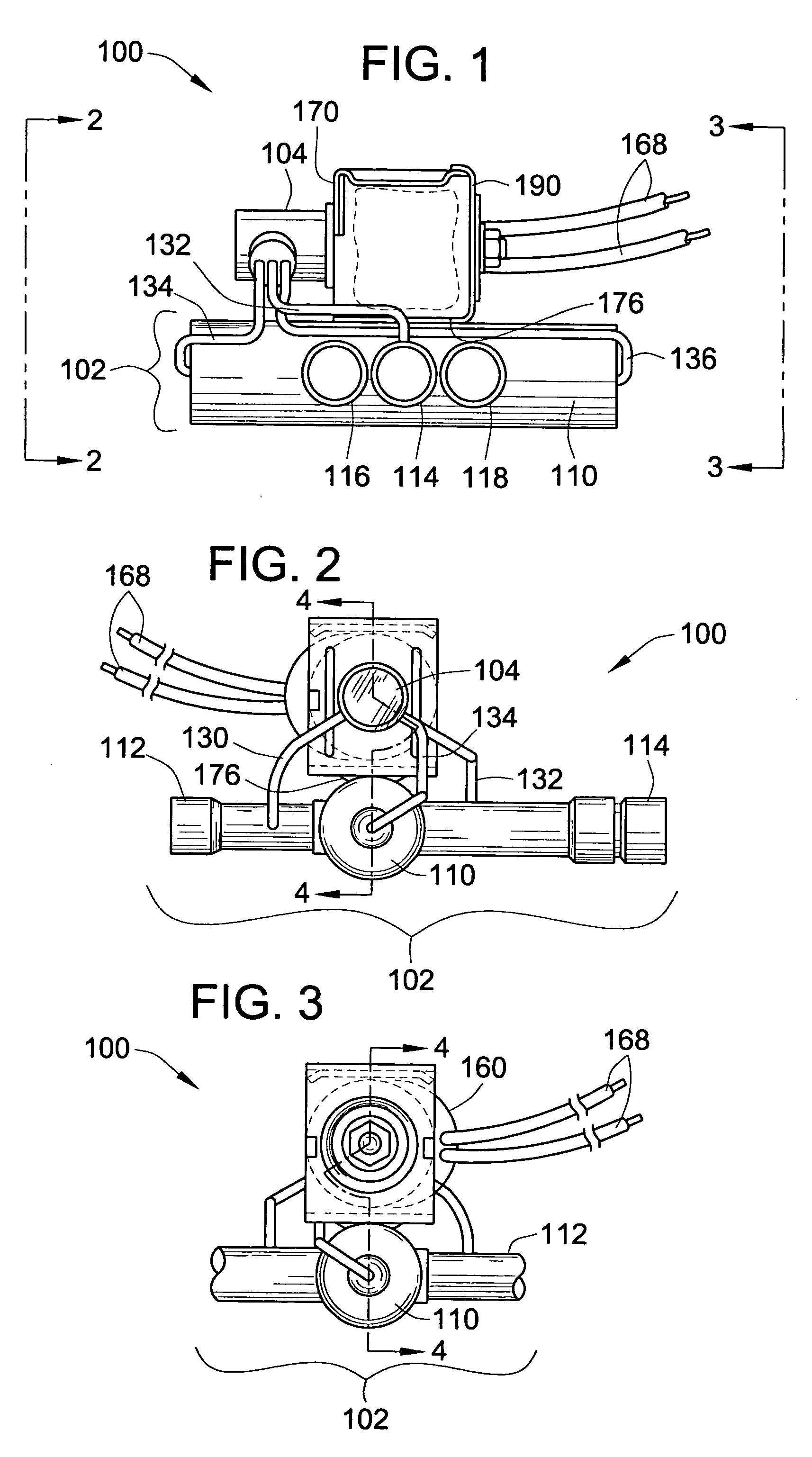
[0021] Now referring to the drawings, wherein like reference numbers refer to like elements, there is illustrated in FIGS. 1-3 an example of a reversing valve assembly 100 for use in a refrigeration system such as a heat pump. Heat pump systems typically include an “inside” heat exchanger located in an “inside” environment, an “outside” heat exchanger located in an outside environment, and a compressor for pressuring and pumping fluid refrigerant through the system. Heat pump systems are operable in two modes: a heating mode in which heat energy is transferred to the inside environment by the inside heat exchanger and a cooling mode in which heat energy is removed from the inside environment. To switch between the heating and cooling modes, the reversing valve assembly 100 is interconnected within the heat pump system and can selectively redirect the fluid refrigerant flow through the system.

[0022] The reversing valve assembly 100 includes a reversing valve 102 for selectively dire...


PUM


Abstract

Provided is a mounting structure for mounting a pilot valve assembly to a flow reversing valve assembly. The mounting structure includes a mounting bracket and a cover plate. Disposed through a face panel of the mounting bracket is an aperture that defines an axis line. The cover plate is generally parallel to and offset from the face panel. A solenoid coil having a central bore is placed between the face panel and the cover plate such that the central bore aligns with the axis line. A pilot valve body included with the pilot valve assembly is partially inserted through the aperture and into the central bore. Extending over the un-inserted portion of the pilot valve body is a sleeve including a spring. The sleeve and spring are arranged such that the spring urges the mounting bracket, the solenoid coil, and the cover plate toward one another.

Description

FIELD OF THE INVENTION [0001] This invention pertains generally to reversing valves and more particularly to reversing valves having a solenoid-operated pilot valve for controlling operation of the reversing valve. BACKGROUND OF THE INVENTION [0002] Reversing valve assemblies are typically used in fluid flow systems in which a fluid is directed to flow in various alternative loops or circuits. For instance, heat pumps are specialized refrigeration systems that can be selectively configured to operate in either of two different modes. In the first mode, known as the cooling mode, energy in the form of heat is removed from an “inside” environment and transferred to an “outside” environment. In the second mode, known as the heating mode, heat energy is transferred to the inside environment. To convey the heat energy, the heat pump system utilizes a compressor to circulate fluid refrigerant through a closed-circuit system that includes heat transfer coils located in each environment. In...

Claims


Application Information

Patent Timeline
Patent Type & Authority Applications(United States)
IPC IPC(8): F16K11/065
CPCF16K11/0655F25B41/046F16K31/061Y10T137/7504Y10T137/86839F25B41/26F16K31/02F16K11/065
Inventor MORENO, JACK A.
Owner ZHEJIANG SANHUA CLIMATE & APPLIANCE CONTROLS GRP CO LTD
Why Eureka
Try Eureka