Circuit arrangement for power distribution in a motor vehicle

A technology for circuit devices and motor vehicles, which is applied to battery circuit devices, circuit devices, motor vehicles, etc., to achieve the effect of reducing energy loss and simplifying circuit devices

Inactive Publication Date: 2012-05-16
BRUSA ELECTRONICS AG
View PDF6 Cites 7 Cited by
  • Summary
  • Abstract
  • Description
  • Claims
  • Application Information

AI Technical Summary

Problems solved by technology

The desire for engine power of 100kW or more presents a particular challenge to the designers of these vehicles

Method used


Image

  • Circuit arrangement for power distribution in a motor vehicle
  • Circuit arrangement for power distribution in a motor vehicle
  • Circuit arrangement for power distribution in a motor vehicle

Examples


Embodiment Construction

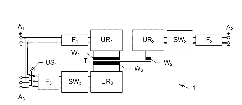
[0064] figure 1 A first exemplary embodiment of the circuit arrangement 1 according to the invention is shown. It consists of three magnetically coupled windings W 1 , W 2 and W 3 Transformer T 1 . In the preferred embodiment shown, they can be wound on a common magnetic core. However, this is by no means necessary, and the magnetic coupling can also be realized in other ways. In each case, the first converter ur 1 , the second converter UR 2 and the third converter UR 3 with the three windings W 1 , W 2 and W 3 connected. The first converter UR 1 via the first filter F 1 First connection A to a first power supply for the interior of the motor vehicle or on-board power supply 1 connected. The second converter UR 2 via voltage transformer SW 2 and the second filter F 2 Second connection A to a second power supply for the interior of the motor vehicle or on-board power supply 2 connected. Finally, the third converter UR 3 via voltage transformer SW 3 and ...


PUM


Abstract

A circuit arrangement (1) for power distribution in a motor vehicle is described, which comprises a transformer(T 1, T 1a..T 1n )having at least three transformer windings(W 1, W 1a..W 1n, W 2, W 2a..W 2n, W 3, W 3a..W 3n ). A first and second on- board supply inside the vehicle and a power supply which is outside the vehicle can be connected to the circuit arrangement (1), which supplies are coupled via the transformer windings (W 1, W 1a..W 1n, W 2, W 2a..W 2n, W 3, W 3a..W 3n ) and converters(UR 1, UR 2, UR 2a..UR 2n, UR 3, UR 3a..UR 3n ). The third converter (UR 3, UR 3a..UR 3n ) can be connected via a first change-over switch(US 1, US 1 ')alternatively to the first on- board supply inside the vehicle or to the power supply outside the vehicle. Aplurality of first converters(UR 1 ) and/or a plurality of secondconverters(UR 2, UR 2a..UR 2n ) and/or a plurality of thirdconverters(UR 3, UR 3a..UR 3n )each being connected to the transformer windings(W 1, W 1a..W 1n, W 2, W 2a..W 2n, W 3, W 3a..W 3n )can be switched in series or in parallel are provided.

Description

[0001] This application claims priority from, and serves as a formal application of, earlier U.S. Provisional Application No. 61 / 221,028, filed June 26, 2009; this application also claims earlier Swiss National Application No. 61 / 221,028, filed September 1, 2009. Priority of 0982 / 09. The entire contents of Swiss Application No. 0982 / 09 and US Application No. 61 / 221,028 are hereby incorporated by reference, for all intents and purposes, as if equivalently set forth herein. technical field [0002] The present invention relates to a circuit arrangement for power distribution of motor vehicles, more particularly for electric vehicles, said circuit arrangement comprising: [0003] - a transformer having at least three magnetically coupled transformer windings, [0004] - a first connection for a first on-board power supply which is inside the motor vehicle and which is coupled via a first converter to a first transformer winding, [0005] - a second connection for a second on-bo...

Claims


Application Information

Patent Timeline
Patent Type & Authority Applications(China)
IPC IPC(8): B60L11/18H02J7/02H02J7/00H02J7/14H02M3/00
CPCH02M2001/007B60L11/1811H02J7/0054B60L11/182H02J7/1423Y02T10/7055Y02T90/14H02J7/0013Y02T90/121Y02T90/127B60L11/1824Y02T10/7005H02M3/33592H02J7/022H02M3/33569H02M2001/0074H02J2007/0059H02M3/00Y02T10/92Y02T90/122B60L11/1818Y02T10/7094B60L2200/26Y02T10/7072B60L53/16B60L53/20H02J2207/20H02J7/342B60L53/122H02J7/02Y02T10/70Y02T90/12H02M1/0074H02M1/007H02M3/33573B60Y2200/91
Inventor 阿克塞尔·克劳泽
Owner BRUSA ELECTRONICS AG
Why Eureka
Try Eureka