Pressure container and pressure accumulating/buffer apparatus

a technology of pressure accumulating and buffer apparatus, which is applied in the direction of accumulator installation, actuator accumulator, pipe element, etc., can solve the problems of large steel pipe and heavy weigh

Active Publication Date: 2006-02-23
NHK SPRING CO LTD
View PDF16 Cites 30 Cited by
  • Summary
  • Abstract
  • Description
  • Claims
  • Application Information

AI Technical Summary

Benefits of technology

[0011] It is an object of the present invention to form a joint portion having sufficient strength of a welded portion by obtaining large welding load and uniform contact in resistance welding even when a thick member is used and a large welding current is electrified.

Problems solved by technology

Further, in the case of the thick steel pipes, in order to obtain the strength of the welded portion by CO2 welding, TIG welding and the like of the outer peripheral surface, the steel pipes become large and heavy.

Method used


Image

  • Pressure container and pressure accumulating/buffer apparatus
  • Pressure container and pressure accumulating/buffer apparatus
  • Pressure container and pressure accumulating/buffer apparatus

Examples


Embodiment Construction

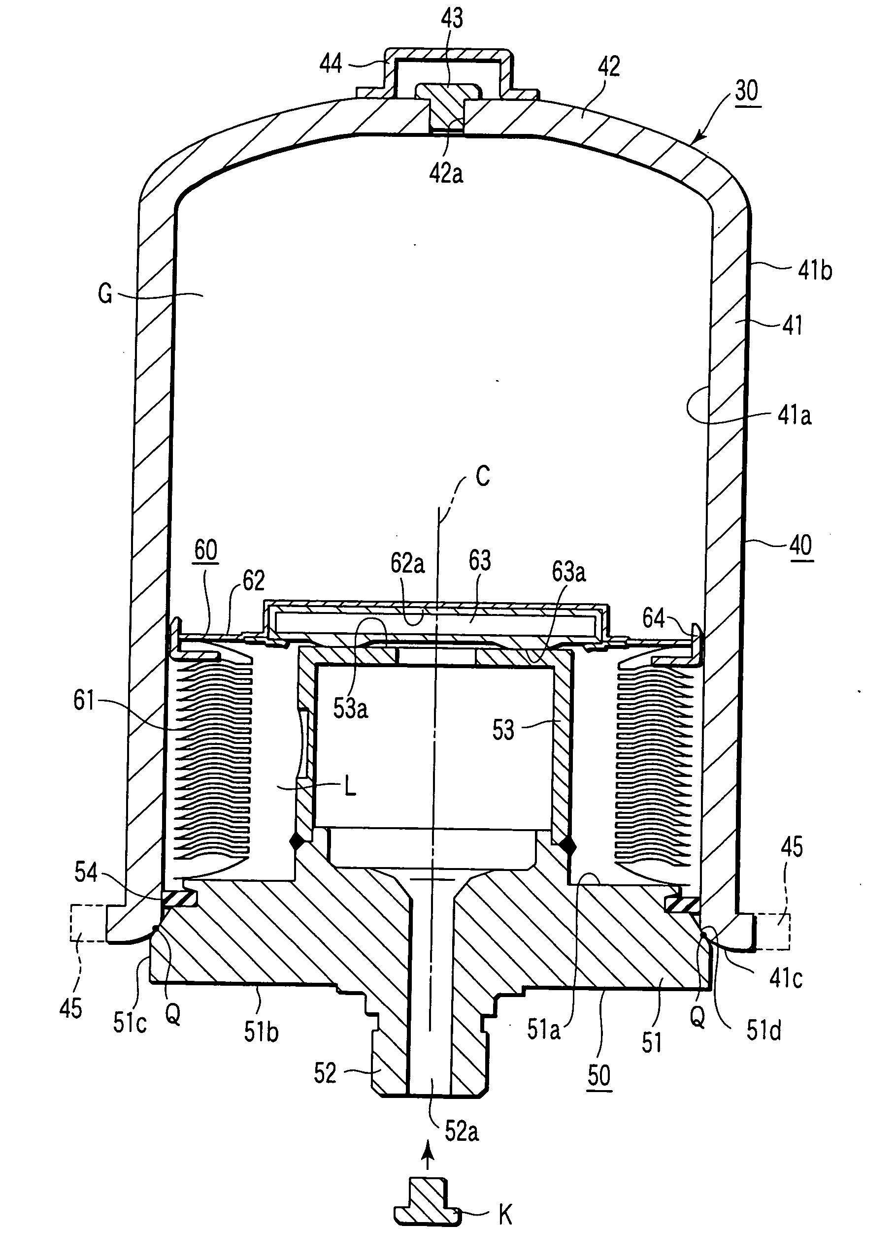
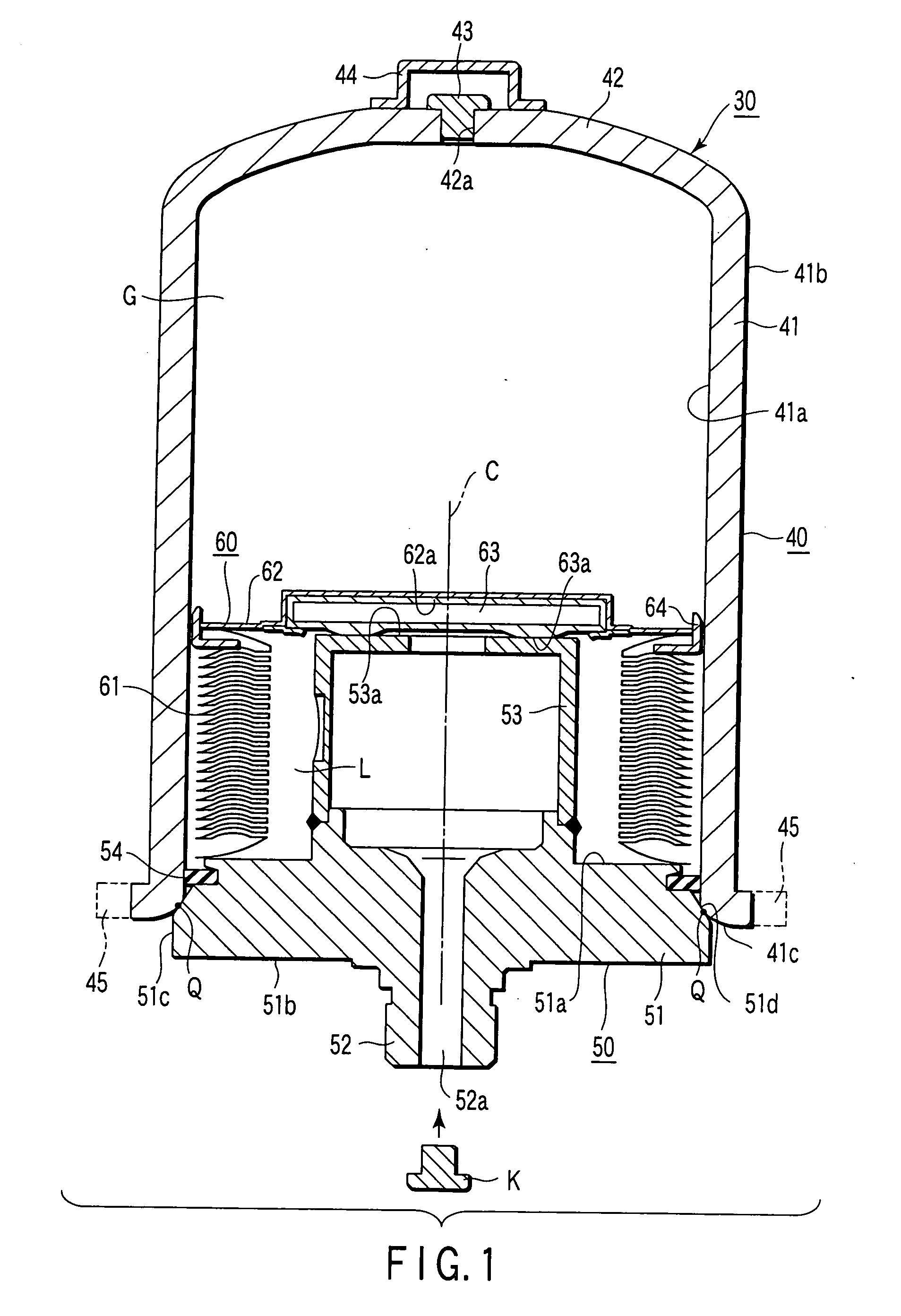
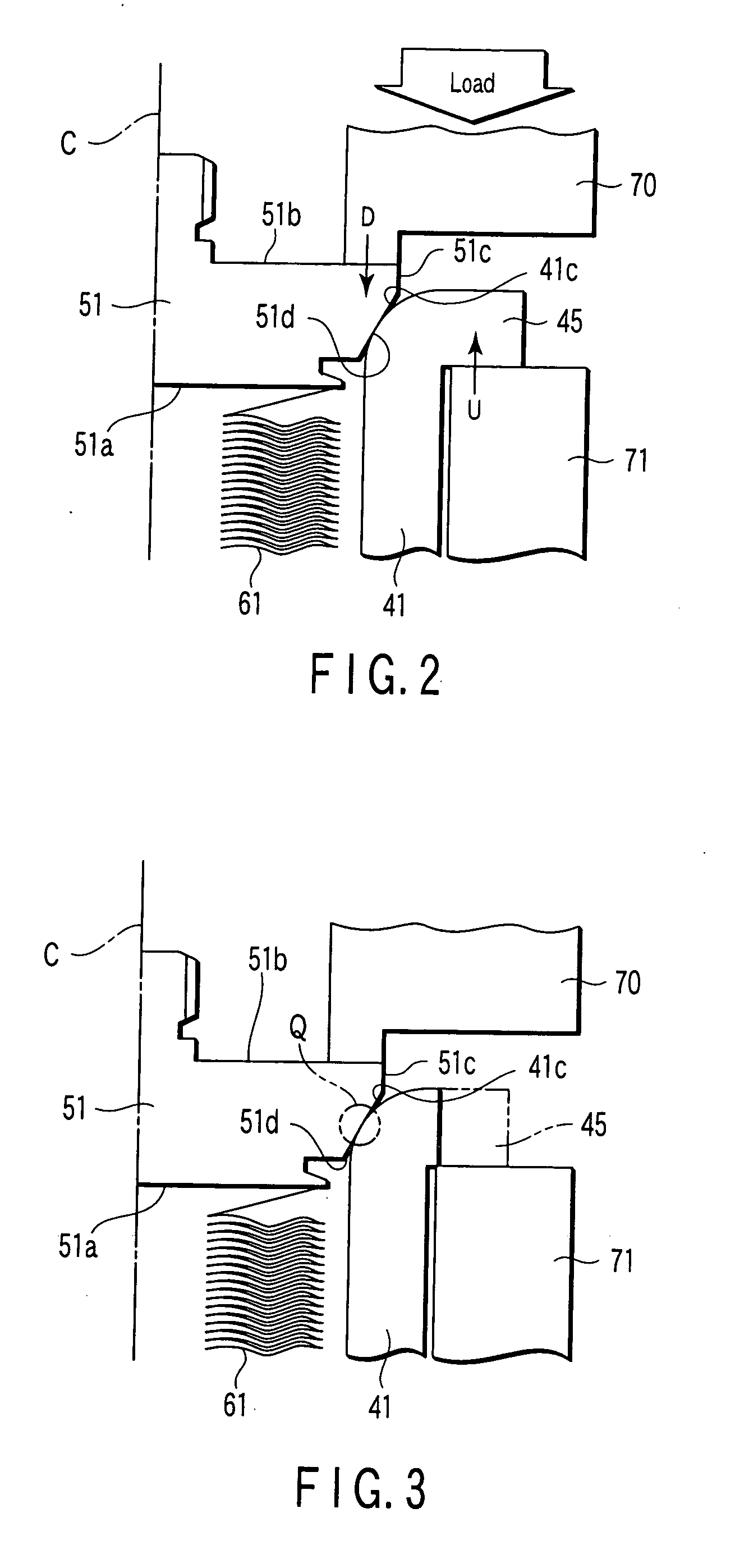
[0024]FIG. 1 is a longitudinal section illustrating an accumulator (pressure accumulating / buffer apparatus) 30 according to one embodiment of the present invention, and FIG. 2 is a longitudinal section typically illustrating a joint portion Q between a steel pipe 40 and an end plate 50 incorporated into the accumulator 30. G in FIG. 1 designates a gas chamber (air chamber), and L designates an oil chamber (liquid chamber).

[0025] The accumulator 30 has the steel pipe (contour member) 40 which has a cylindrical shape with a bottom, an end plate (cover body) 50 which is fitted into an opening of the steel pipe 40, and a bellows mechanism 60 housed in the steel pipe 40. The steep pipe 40 and the end plate 50 compose the pressure container, and a tapered surface 41c, mentioned later, of the steep pipe 40 and a tapered surface 51d, mentioned later, of the end plate 50 are jointed by resistance welding so that the joint portion Q is formed.

[0026] The steel pipe 40 is formed by joining a ...


PUM


Abstract

A pressure container has a steel pipe and an end plate that is formed with a joint portion by allowing its tapered surface to touch a tapered surface of an opening end of the steel pipe so as to block the opening end. The steel pipe has a flange portion which can be cut at the opening end of the steel pipe, and the joint portion is allowed to touch the flange portion. The flange portion is pressed against the opening end along an axial direction so as to touch the end plate, and while the end plate is being pressed against the steel pipe along the axial direction, an electric current is applied so that welding is carried out.

Description

CROSS-REFERENCE TO RELATED APPLICATIONS [0001] This application is based upon and claims the benefit of priority from prior Japanese Patent Application No. 2004-242565, filed Aug. 23, 2004, the entire contents of which are incorporated herein by reference. BACKGROUND OF THE INVENTION [0002] 1. Field of the Invention [0003] The present invention relates to a pressure container and a pressure accumulating / buffer apparatus such as an accumulator which are used in an automobile and an industrial machine, and particularly relates to them where a welded portion between an end plate and a body portion is uniform. [0004] 2. Description of the Related Art [0005] Accumulators (pressure accumulating / buffer apparatus) are used in hydraulic circuits and shock absorbers of hydraulic control apparatuses. In the accumulators, insides of pressure containers are generally divided into gas chambers and oil chambers by bellows, and pressure fluctuation in oil flowing into the oil chambers are buffered ...

Claims


Application Information

Patent Timeline
Patent Type & Authority Applications(United States)
IPC IPC(8): F16L55/04
CPCF15B1/103F15B1/106F15B1/22F15B2201/605F15B2201/3153F15B2201/3158F15B2201/205F15B1/08
Inventor SHIMBORI, TAKEYOSHIMIZUKAMI, HIROSHIYAMADA, KOICHIROINOUE, KYOHEI
Owner NHK SPRING CO LTD
Why Eureka
Try Eureka