Method for the feed of cellulose chips during the continuous cooking of cellulose

a technology of cellulose chips and feed, which is applied in the direction of finely divided material pretreatment, digesters, textiles and paper, etc., can solve the problem of unnecessary separation of equipment at the top of the treatment vessel

Inactive Publication Date: 2006-02-23
METABO PAPER SWEDEN
View PDF20 Cites 11 Cited by
  • Summary
  • Abstract
  • Description
  • Claims
  • Application Information

AI Technical Summary

Benefits of technology

[0008] A further aim is to make an input system possible where a top separator at the top of the impregnation vessel or the digester is not necessary.

Problems solved by technology

According to one alternative embodiment, the method is applied to processes with high L / W ratios during the impregnation or the cooking, also making separation equipment at the top of the treatment vessel unnecessary.

Method used


Image

  • Method for the feed of cellulose chips during the continuous cooking of cellulose
  • Method for the feed of cellulose chips during the continuous cooking of cellulose
  • Method for the feed of cellulose chips during the continuous cooking of cellulose

Examples


Embodiment Construction

[0013] Description of the drawings:

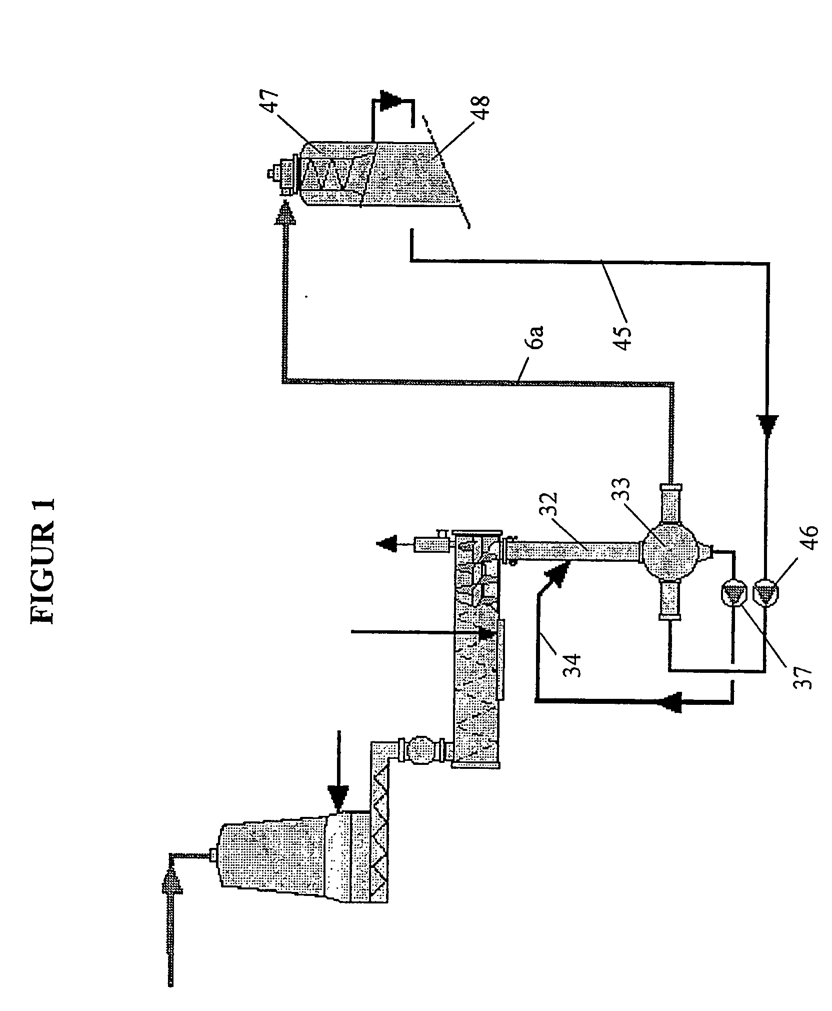
[0014]FIG. 1 shows schematically a conventional feed system with an HP feeder together with a chip chute and a transfer flow.

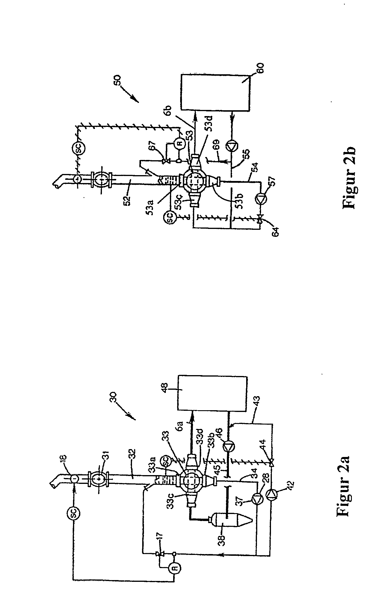
[0015]FIGS. 2a, 2b show schematically a feed system according to a technology developed later comprising both a chute flow and a transfer flow with return line (according to U.S. Pat. No. 6,120,646).

[0016]FIG. 3 shows in detail an arrangement around the HP feeder (according to U.S. Pat. No. 6,120,646).

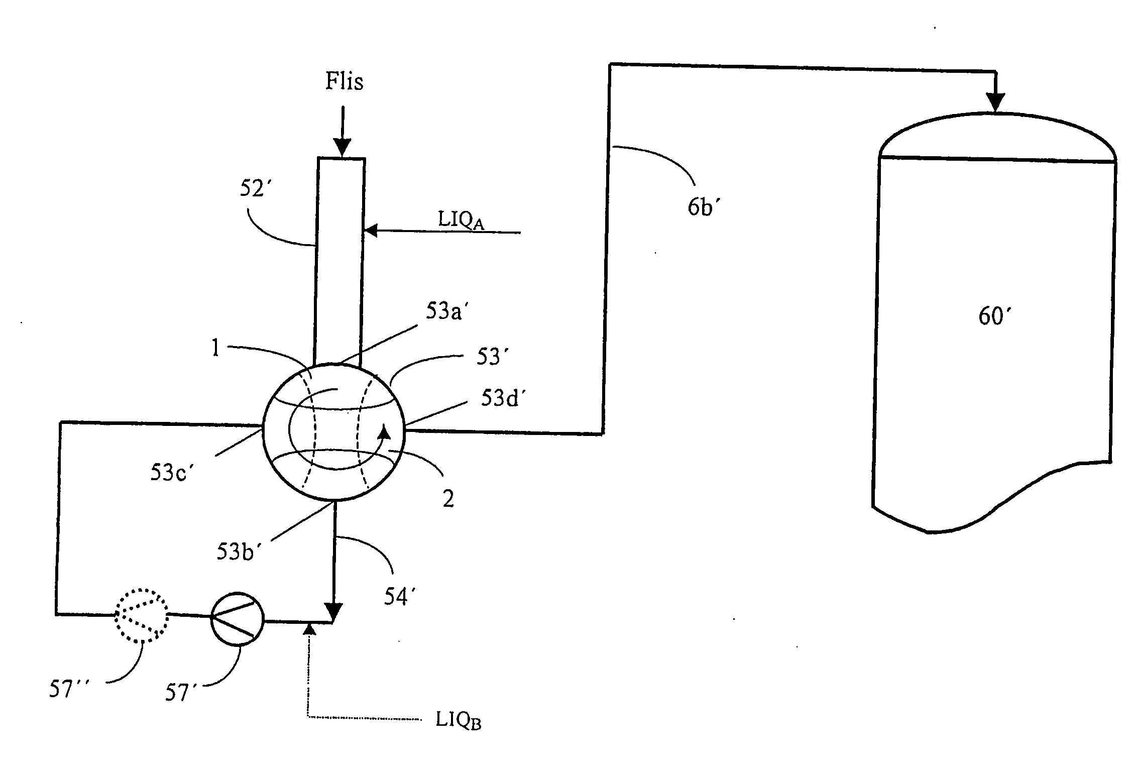
[0017]FIG. 4 shows one preferred embodiment of a feed system according to the invention.

[0018]FIG. 5 shows an alternative embodiment according to the invention in which the method is applied for an HP feeder located between two treatment vessels.

[0019]FIG. 1 shows schematically a feed system according to the prior art with an B[P feeder 33 together with a chips flow 34 and a transfer flow (6a, 45). The transfer flow is constituted by a transfer line 6a for transport of chips that have been formed into a slurry with a transp...


PUM

PropertyMeasurementUnit
pressureaaaaaaaaaa
pressureaaaaaaaaaa
densityaaaaaaaaaa

Abstract

The method is for feeding a chips-slurry from a low-pressure to a high-pressure system during the continuous cooking of chemical cellulose pulp. The feed takes place through a sluice feeder 53′ between these systems. The sluice feeder is provided with a rotor with through-pockets 1, 2 that are alternately connected with the low- or the high-pressure system. A recirculation line 54′, that has a high-pressure pump 57′, extends from the first outlet 53b′ of the sluice feeder to the second inlet 53c′ of the sluice feeder for transporting the fluid that has been expelled from the pockets of the sluice feeder when these are located in their first position. The fluid expels the chips mixture from the pockets of the sluice feeder in their second position and is essentially exclusively constituted by the fluid that has been expelled from the pockets in their first position.

Description

TECHNICAL AREA [0001] The invention concerns a method for the feed of cellulose chips during the continuous cooking of cellulose according to the introduction to claim 1. THE PRIOR ART [0002] When cooking cellulose chips in continuous digesters, the chips are transported from a feed system at atmospheric pressure, or a pressure slightly over atmospheric pressure, by what is known as a “transfer flow” to an impregnation vessel or a digester at a considerably higher pressure. Transport in the transfer flow is made possible by the chips being combined with a transport fluid, preferably a process fluid, to form a slurry; the transport fluid being subsequently separated from the chips in separation equipment, normally denoted the “top separator”, when it has reached the impregnation vessel or the digester. The transport fluid is returned to the feed system through a return line. The transfer flow has for many years comprised a special type of sluice feeder, known as a high-pressure feede...

Claims


Application Information

Patent Timeline
Patent Type & Authority Applications(United States)
IPC IPC(8): D21C7/06D21C3/24
CPCD21C7/06
Inventor GUSTAVSSON, LENNARTSNEKKENES, VIDAR
Owner METABO PAPER SWEDEN
Why Eureka
Try Eureka