Pressure exchange apparatus with integral pump

a technology of pressure exchange apparatus and pump, which is applied in the direction of multi-cylinder pump, rotary piston liquid engine, machine/engine, etc., can solve the problems of high value of pressure energy contained in pressure energy, long and trouble-free operation life, and high cost of use of separate boost pump according to the prior ar

Inactive Publication Date: 2006-02-23
SHUMWAY SCOTT
View PDF6 Cites 64 Cited by
  • Summary
  • Abstract
  • Description
  • Claims
  • Application Information

AI Technical Summary

Benefits of technology

[0013] In accordance with a general aspect of the present invention a pressure exchange device for the transfer of a fluid is provided comprising a high pressure boost unit which is comprised of a high pressure conduit in fluid communication with an impeller. The impeller is configured to raise the pressure of a fluid received through a high pressure inlet port. A low pressure conduit disposed on the high pressure boost unit is in fluid communication with a low pressure fluid source. A pressure exchange unit is further provided which comprises a spinning rotor having a first and second conduit running therethrough, wherein the first and second conduit intermittently align with the high pressure conduit and the low pressure conduit as the rotor spins. A shaft running coaxially through the pressure exchange device is provided with the shaft being further connected to the rotor and the impeller. A motive force is attached to the shaft to provide the energy to spin the rotor and the impeller.
[0014] In accordance with another general aspect of the present invention, a system for the filtration of contaminated water to produce potable water is provided which comprises a low pressure pump configured to pump the contaminated water to a high pressure pump. A high pressure pump configured to receive contaminat

Problems solved by technology

The device employed for achieving this highly efficient transfer has a long and trouble free operating life which is not interrupted by the plugging and fouling of valves, or the binding or freezing of sliding pistons or the like.
While the high pressure brine is no longer useful in th

Method used


Image

  • Pressure exchange apparatus with integral pump
  • Pressure exchange apparatus with integral pump
  • Pressure exchange apparatus with integral pump

Examples


Embodiment Construction

[0019] The following detailed description is of the best currently contemplated modes of carrying out the invention. The description is not to be taken in a limiting sense, but is made merely for the purpose of illustrating the general principles of the invention, since the scope of the invention is best defined by the appended claims.

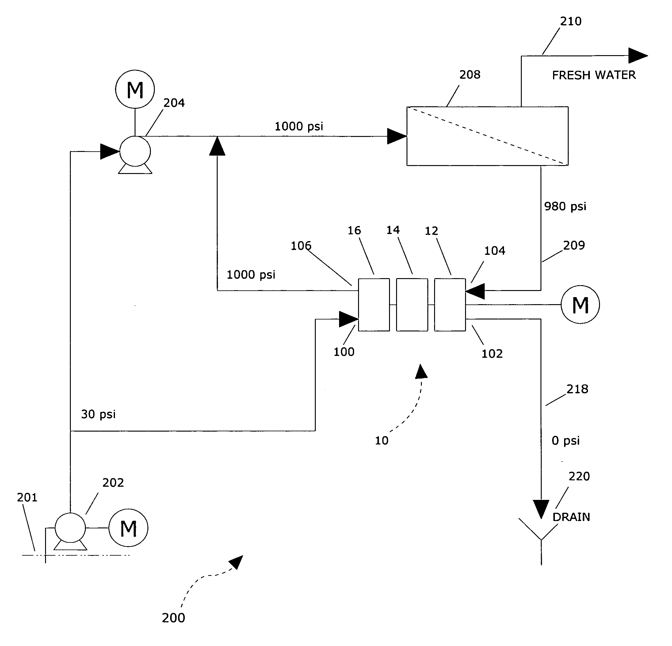
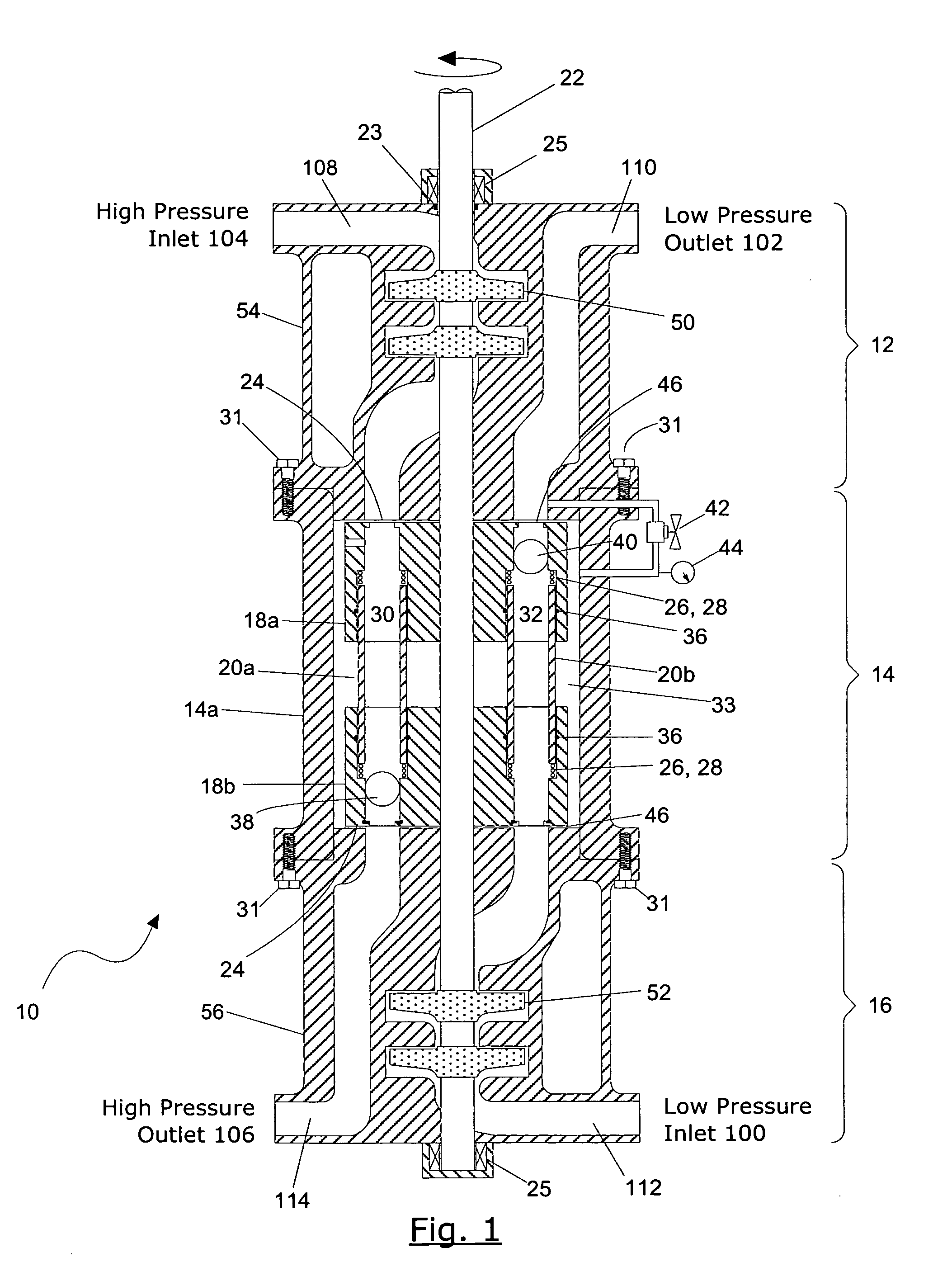
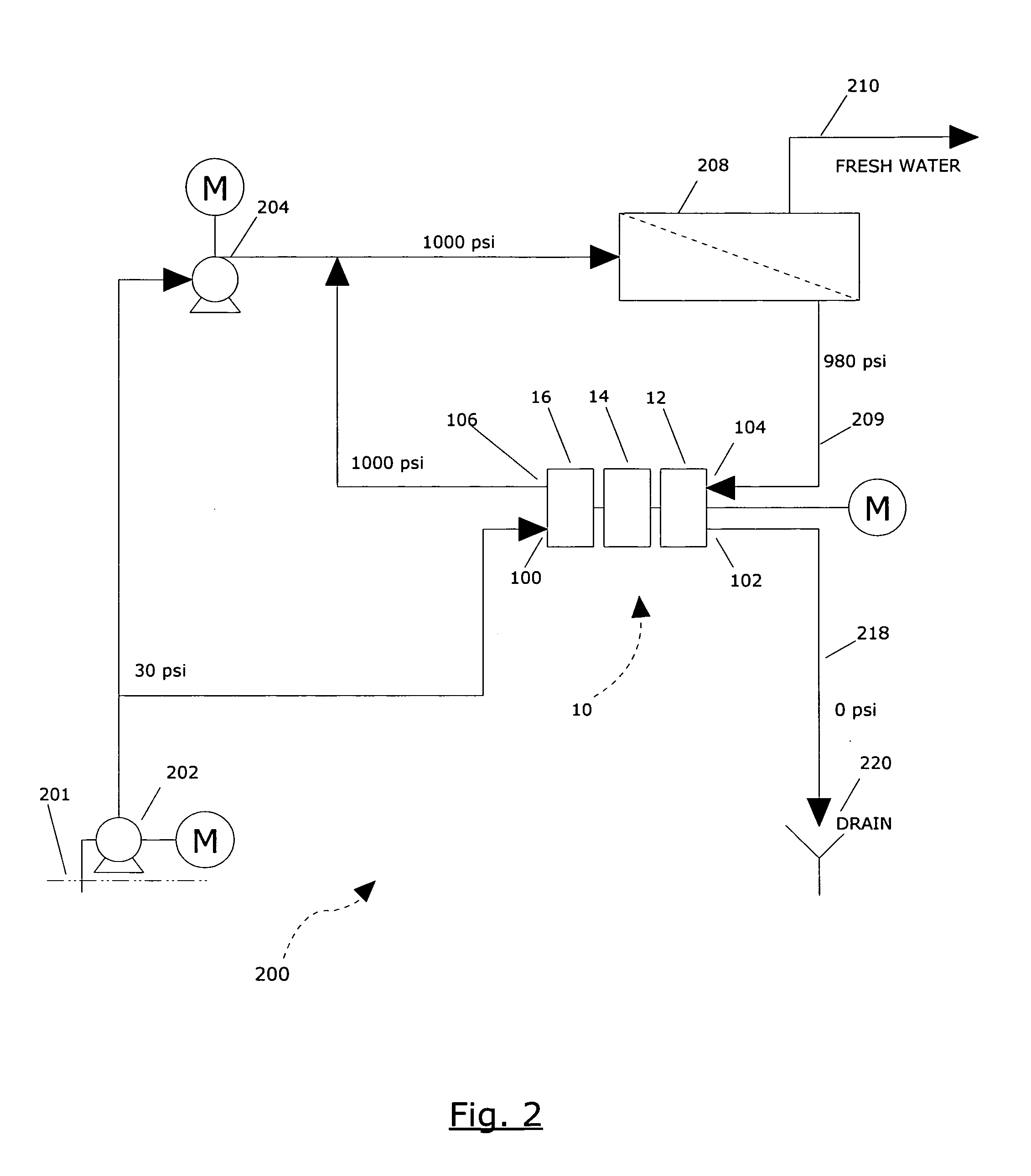
[0020] Referring to FIG. 1, which depicts a simplified cross-sectional view of a pressure exchange device 10 with an integral inlet and outlet boost pump in accordance with the present invention.

[0021] The pressure exchange device 10 comprises three main sections, a high pressure boost pump unit 12, a pressure exchange unit 14 and a low pressure boost pump 16. A single shaft 22 runs coaxially through all three sections and is attached to a motive force such as a motor (not shown). The shaft 22 is connected to various spinning parts which will be described in detail later.

[0022] The high pressure boost pump 12 comprises a housing 54 having a high pre...


PUM

PropertyMeasurementUnit
Forceaaaaaaaaaa
Pressureaaaaaaaaaa
Diameteraaaaaaaaaa

Abstract

A pressure exchange device is provided that utilizes an integral high pressure boost pump that is in fluid communication with a pressure exchange unit. An optional low pressure boost pump unit may also be provided. The pressure exchange unit comprises a rotating rotor assembly inside a housing to transfer the pressure of a fluid from one high pressure fluid to another low pressure fluid.

Description

BACKGROUND OF THE INVENTION [0001] This invention relates to pressure exchangers for transfer of energy from one liquid flow to another. More specifically, this invention relates to pressure exchangers having an integral pump for the transfer of energy from one liquid stream to another. [0002] The present invention provides a device that can be appropriately described as an engine for exchanging pressure energy between relatively high and relatively low pressure fluid systems, which the term fluid being defined here as including gases, liquids and pumpable mixtures of liquids and solids. The engine for pressure energy exchange of the present invention is a highly efficient device with well over 90% of the energy of pressurization in a pressurized fluid system being transferred to a fluid system at a lower pressure. The device employed for achieving this highly efficient transfer has a long and trouble free operating life which is not interrupted by the plugging and fouling of valves...

Claims


Application Information

Patent Timeline
IPC IPC(8): B01D65/00
CPCB01D61/06F04B1/20F15B3/00F04B19/20F04F13/00F04B9/10F04D1/06
Inventor SHUMWAY, SCOTT
Owner SHUMWAY SCOTT
Why Eureka
Try Eureka