Power supply system for vehicle
a technology for power supply systems and vehicles, applied in hybrid vehicles, electric generator control, instruments, etc., can solve the problems of increasing the cost of installation of spare systems and the inability to generate electric power
- Summary
- Abstract
- Description
- Claims
- Application Information
AI Technical Summary
Benefits of technology
Problems solved by technology
Method used
Image
Examples
first embodiment
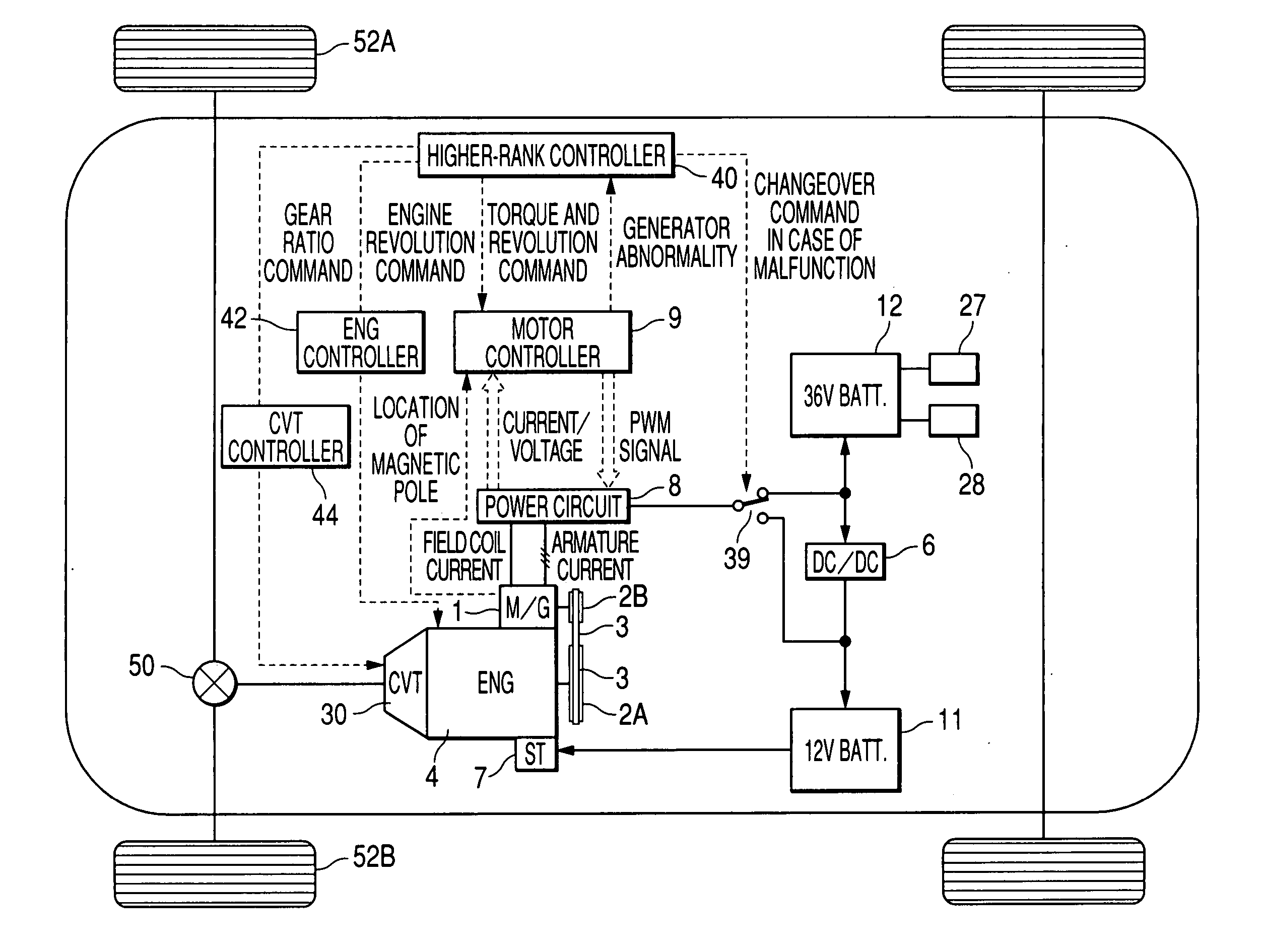
[0052] With reference to FIGS. 1 through 7, configuration of a power supply system for vehicle according to the present invention will be explained.
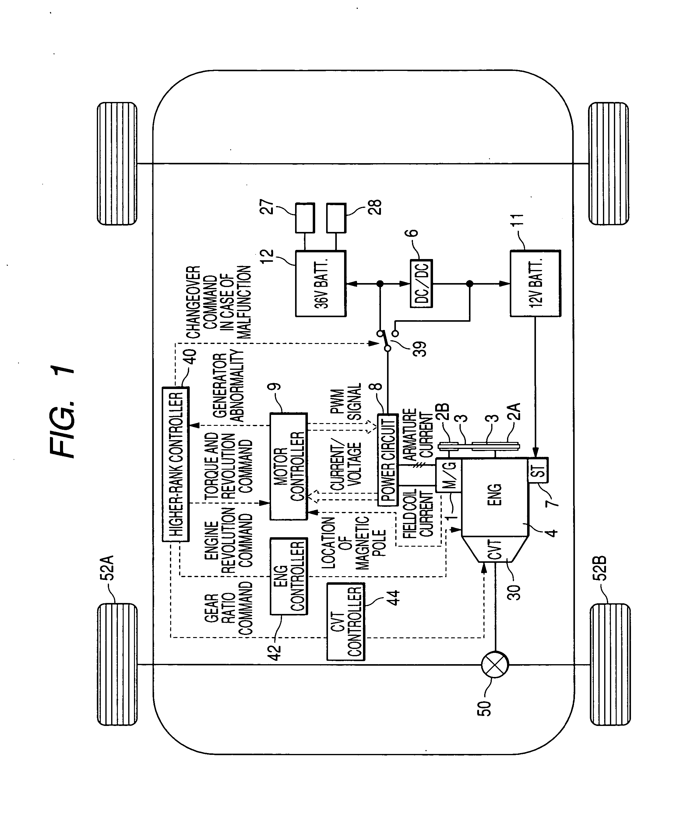
[0053] First, by using FIG. 1, configuration of a vehicle which incorporates a power supply system for vehicle according to this embodiment will be explained.
[0054]FIG. 1 is a block diagram that shows configuration of a vehicle which incorporates a power supply system for vehicle according to a first embodiment of the present invention.
[0055] Rotation speed of an engine 4 is changed by a CVT 30 and transmitted to wheels 52A and 52B via a differential gear 50, thereby running the vehicle. An engine controller 42 controls fuel injection and ignition timing for the engine 4 according to an engine revolution command issued by the higher-rank controller 40. The CVT 30 is controlled by a CVT controller 44 according to a transmission gear ratio command sent by the higher-rank controller 40.
[0056] Rotation of the engine 4 is transmitted to a ...
second embodiment
[0089] Next, with reference to FIGS. 8 through 10, configuration of a power supply system for vehicle which uses a vehicle generator according to the present invention will be explained.
[0090] First, by using FIG. 8, configuration of the major part of the vehicle that incorporates a power supply system for vehicle according to this embodiment will be explained.
[0091]FIG. 8 is a block diagram that shows configuration of the major part of the vehicle that incorporates a power supply system for vehicle according to a second embodiment of the present invention. The same numbers and symbols shown in FIG. 1 indicate the same parts.
[0092] The configuration of the power supply circuit according to this embodiment is different from that of FIG. 4; it does not use a changeover switch. If an abnormality occurs causing field coil current to stop flowing, the higher-rank controller 40 detects the abnormality and issues a command to the continuous and variable transmission unit CVT controller 4...
third embodiment
[0111] Next, with reference to FIG. 11, configuration of a power supply system for vehicle which uses a vehicle generator according to the present invention will be explained.
[0112]FIG. 11 is a block diagram that shows configuration of a power supply system for vehicle according to a third embodiment of the present invention. Items are identical to those in FIGS. 1 and 2 when the same alphanumeric characters are assigned.
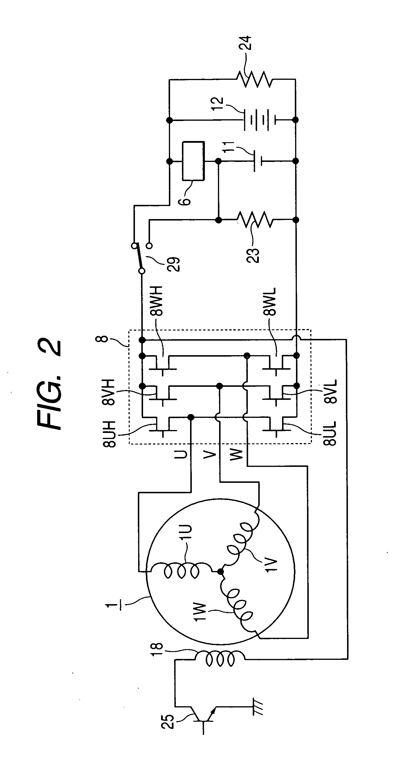
[0113] This embodiment is different from those shown in FIGS. 1 and 2 in that this embodiment uses a commutating circuit which comprises six diodes 31 instead of using a power circuit which comprises MOS-FETs shown in FIG. 2. In this embodiment, since the generator 1A is not used as a motor, it is a simple high-voltage generator. Two power supply systems, 36 V and 12 V, are provided, and the higher-rank controller 40 switches the switch 29 so that the generator 1 charges the high-voltage side 36-V battery 11 during normal operation. The generator 1A generates highe...
PUM
 Abstract
Description
Claims
Application Information
 - R&D
- Intellectual Property
- Life Sciences
- Materials
- Tech Scout
- Unparalleled Data Quality
- Higher Quality Content
- 60% Fewer Hallucinations
Browse by: Latest US Patents, China's latest patents, Technical Efficacy Thesaurus, Application Domain, Technology Topic, Popular Technical Reports.
© 2025 PatSnap. All rights reserved.Legal|Privacy policy|Modern Slavery Act Transparency Statement|Sitemap|About US| Contact US: help@patsnap.com


