Method and apparatus for dynamically reducing end-to-end delay in multi-hop wireless networks in response to changing traffic conditions

a wireless network and traffic condition technology, applied in data switching networks, instruments, frequency-division multiplexes, etc., can solve problems such as inability to overcome, and achieve the effect of reducing the mean end-to-end network transmission delay

Inactive Publication Date: 2006-02-23
LUCENT TECH INC
View PDF9 Cites 40 Cited by
  • Summary
  • Abstract
  • Description
  • Claims
  • Application Information

AI Technical Summary

Benefits of technology

[0007] Both of these illustrative embodiments of the present invention are advantageously centralized, assume that the initial network topology is known, and use traffic-related information to advantageously modify the network topology in incremental steps. Advantageously, the tr

Problems solved by technology

These approaches, however, cannot overcome the problems that result from inherent network “bottl

Method used


Image

  • Method and apparatus for dynamically reducing end-to-end delay in multi-hop wireless networks in response to changing traffic conditions
  • Method and apparatus for dynamically reducing end-to-end delay in multi-hop wireless networks in response to changing traffic conditions
  • Method and apparatus for dynamically reducing end-to-end delay in multi-hop wireless networks in response to changing traffic conditions

Examples


Embodiment Construction

Introduction and Summary

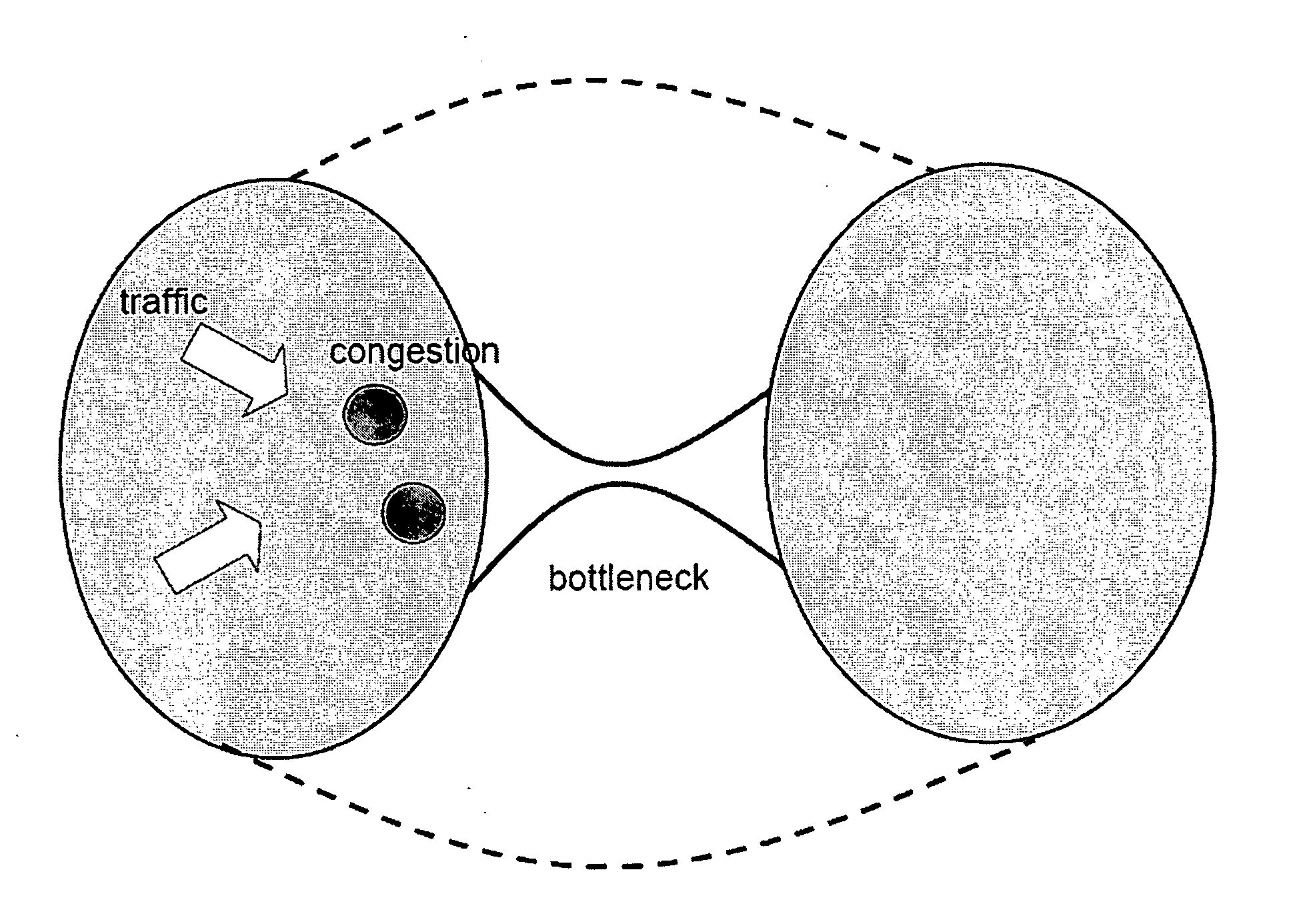
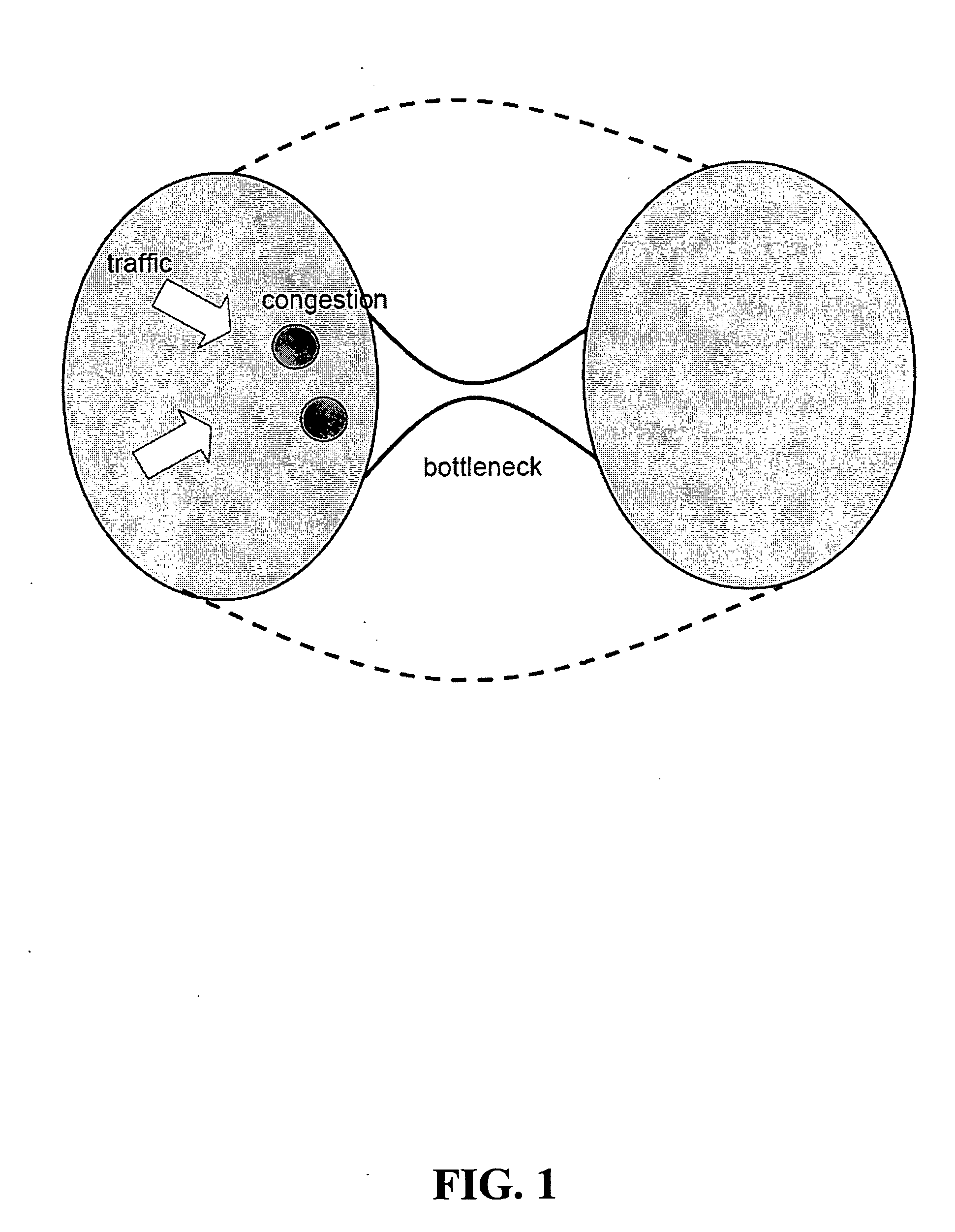
[0013]FIG. 1 shows an abstract view of an illustrative wireless communications network in which a “funneling” effect occurs at a bottleneck. As can be seen in the figure, traffic going across the bottleneck from the left half of the network to the right half of the network has to “squeeze” through links upstream of the bottleneck. This can cause congestion elsewhere in the network (as shown by the darker patches in the figure) even though the bottleneck bandwidth may be high. In accordance with the principles of the present invention, the solution to this problem is to siphon the traffic out early by creating new links (as shown by the dotted lines in the figure) that join network nodes away from the bottleneck link.

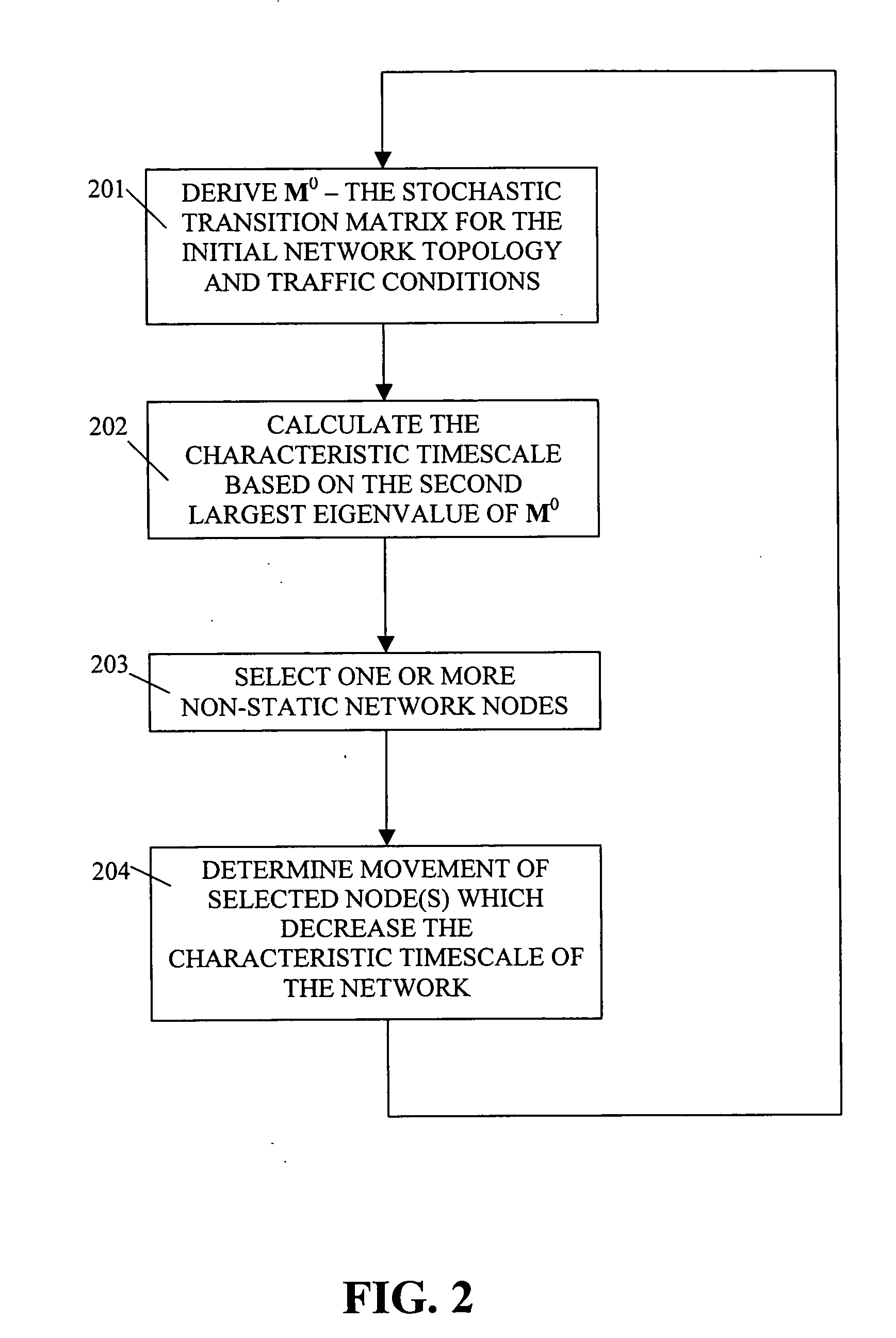
[0014] In order to describe the illustrative embodiments of the present invention, we will first derive a quickly computable metric that we note correlates well with the mean network transit time. Then, in accordance with certain illustrative e...


PUM


Abstract

A method and apparatus for deforming the network topology of a multi-hop wireless network dynamically (i.e., in real time), in response to changing network traffic conditions and in order to advantageously reduce mean end-to-end network (transmission) delay. Two illustrative embodiments of the invention deform the network topology dynamically in response to traffic conditions (i) by changing the network connectivity between the existing network nodes and (ii) by adding one or more new nodes (and associated connections thereto and therefrom) to the network. In both cases, the traffic conditions may be fed into the algorithm in real time as, for example, a set of queue length measurements. Then, in response, the network is advantageously reorganized into a configuration that reduces the mean end-to-end network transmission delay.

Description

FIELD OF THE INVENTION [0001] The present invention relates generally to wireless communications networks and more particularly to a method and apparatus for dynamically reducing transmission delays in multi-hop wireless networks in response to changing traffic conditions by changing network topology. BACKGROUND OF THE INVENTION [0002] Recent developments in wide-area wireless technologies (such as, for example, the well known IEEE 802.16 standard) have led to considerable interest in the construction of multi-hop wireless mesh networks. In particular, such networks are being proposed and studied as an enabling technology for multiple applications such as machine-to-machine (M2M) communications, sensor networks, and Internet access for consumers and businesses, among others. [0003] The standard architecture for such wireless mesh networks involves routing packets over multiple wireless hops until they reach the destination or a wired network core. The intermediate nodes may be mobil...

Claims


Application Information

Patent Timeline
IPC IPC(8): H04J3/14H04L12/26
CPCH04L45/02H04W84/18H04W40/34H04L45/121
Inventor BASU, ANINDYABOSHES, BRIANMUKHERJEE, SAYANDEVRAMANATHAN, SHARAD
Owner LUCENT TECH INC
Why Eureka
Try Eureka